Chapter 2 Operating Principles
2-2. Operation of Control Parts
CL-S700/CL-S703/CL-S700R 2-34
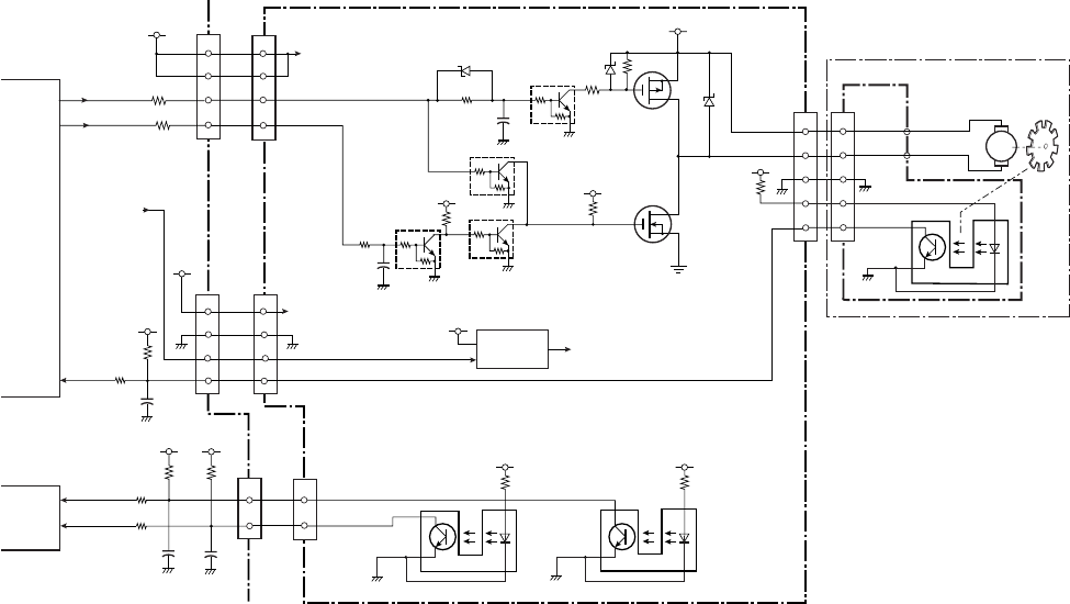
(3) Rewinder motor driver (CL-S700R only)
This is a driving circuit to drive the rewinder motor (DC motor). The following illustration shows
a simplified circuit.
Rewinder motor ON/OFF status is controlled by DCMTR1 and DCMTR0 signals sent from pins
35 and 40 of U1 (CPU).
Motor ON: DCMTR1=L and DCMTR0=H
Motor OFF (free): DCMTR1=L and DCMTR0=L
Braking: DCMTR1=H (DCMTR0=L/H)
When DCMTR1 signal is “Low”, Q502 turns OFF and Q501 turns OFF. When DCMTR0 signal
is “High”, Q506 turns ON, Q505 turns OFF and, if Q503 is OFF (DCMTR1 signal is “Low”),
Q504 turns ON and the rewinder motor is turned.
Rewinder Full detection:
The form sensor (photo interrupters PS501 and PS502) on the “SA, Rewinder PCB” is used to
detect the diameter of wound liner (or the amount of liner) at the flange in the following four
stages. As the diameter increases, the Measure Flap Plate turns backward and engages with
PS501 and PS502.
1st stage: PS501: ON, PS502: OFF
2nd stage: PS501: ON, PS502: ON
3rd stage: PS501: OFF, PS502: ON
4th stage (Full): PS501: OFF, PS502: OFF
The 1st to 3rd stages are used to control the rewinder motor speed as mentioned on the next
page. The 4th stage is the Full state.
The outputs of PS501 and PS502 are fed to pins 84 (HPSENS0) and 85(HPSENS1) of U14
(Custom IC). When the Measure Flap Plate engages PS501/PS502, the light emitted from the
LED is blocked by the plate and PS501/PS502 turns ON and pin 84/85 becomes “High”.
J504
3
2
J502
[SA, Rewinder Motor]
J701
2
3
M
Rewinder Motor
+3.3V
R163
R165
3
[Main PCB]
MTENC
U1 CPU
P72
176
C99
2
J16
5
6
7
Blade
1
3
5
6
7
+5.0V
R512
Q501
2SJ668
+RW
R505
D503
Q504
2SK4033
Q505
DTC114EM
Q502
DTC114EM
+5.0V
R507
R504
C506
+5.0V
R508
7
J501
7
6
J15
DCMTR1
DCMTR0
R506
Q503
DTC114EM
MTENC
35
DCMTR1
DCMTR0
40
PCS7
PCS4
R157
R156
4
+5.0V
4
+5.0V
1
1
MTREF
6
+24.0V
+24.0V
+24.0V
U501
Switching Regulator
+RW
[Rewinder PCB]
D502
DTC114EM
Q506
C507
R509
D504
ADJ
R510
+5.0V
PS501
R511
+5.0V
PS502
8
J501
8
9
J15
SW6
9
MTREF
(+RW Control)
U14
Custom IC
+3.3V
R153
R159
84
SW5
+3.3V
R154
R158
HPSENS0
85
C97
J15
C96
HPSENS1
1
1
2
2
HPSENS0
HPSENS1
PS701


