


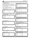
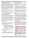
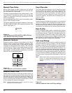
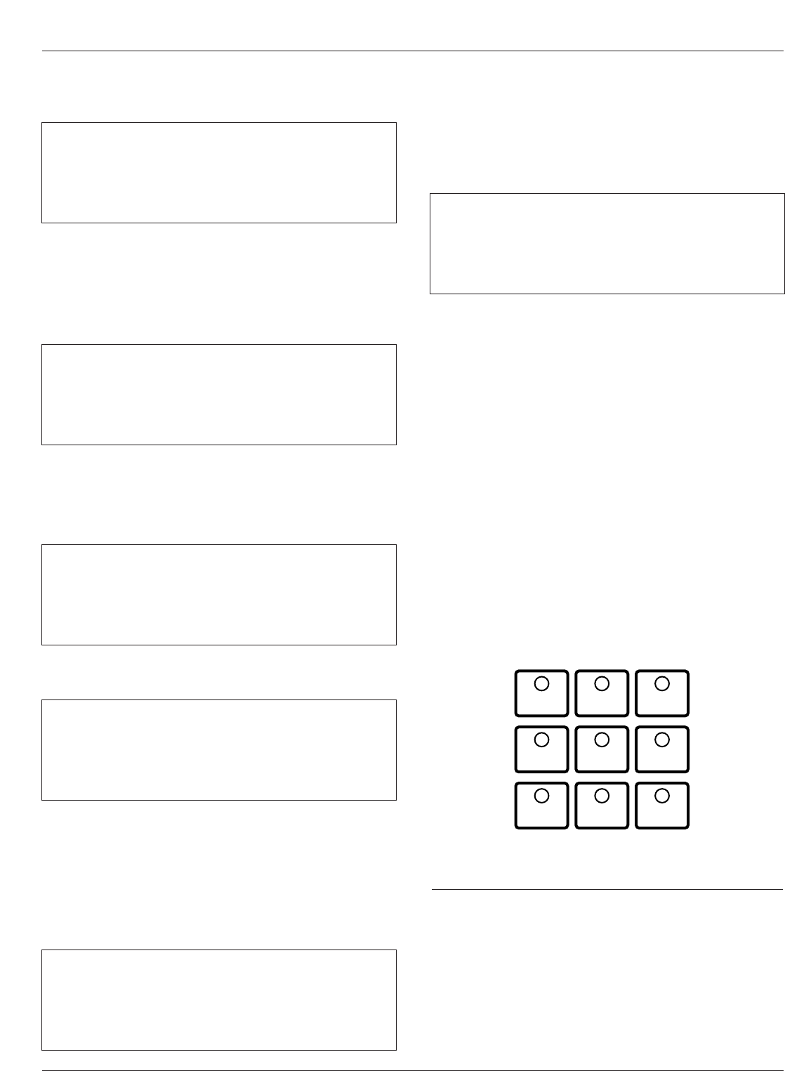
Operation/Indication Pushbuttons
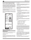
Nine frequently used features are provided on the control
operator panel (Figure 7).
Note: These features are activated from the keypad, control
interface software or SCADA signal.
To initiate an operation from the operator panel, press the
CHANGE/LAMP TEST key to enter the CHANGE mode.
The operator has 10 seconds to select an operation and
modify settings. If no changes are made, the control will
return to its operational state prior to entering the
CHANGE mode. This prevents accidental changing of
settings.
Red LEDs located on each switch indicate the status of
the function, regardless of local or remote activation. For
example, if Cold Load Pickup was activated from a
SCADA signal, the red indicator would illuminate even
though it was not activated from the operator panel.
Note: Operation LEDs activated from local or remote sources
do not illuminate when the front panel is in the power-
save mode.
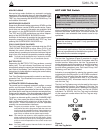
GND TRIP BLOCKED
Ground Trip Blocked is activated by pressing the
CHANGE/LAMP TEST key, then pressing the GND TRIP
BLOCKED key. The red indicator illuminates.
Kyle Form 5, Form 5 UDP, Form 5 DC NOVA Recloser Control Installation and Operation Instructions
12
GND TRIP
BLOCKED
NON
RECLOSING
SUPERVISORY
BLOCKED
COLD LOAD
PICKUP
BLOCKED
BATTERY
TEST
FAST
TRIPS
DISABLED
ALTERNATE
PROFILE
NO. 1
ALTERNATE
PROFILE
NO. 2
ALTERNATE
PROFILE
NO. 3
Figure 7.
Operation/indication pushbuttons.
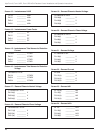
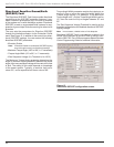
37 Ph3-4 Min ____________A
Time Date
Ph5-6 Min ____________A
Time Date
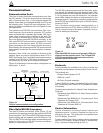
40 – Comm Port 2 ______
Protocol _______
Speed _______
Address _______
41 – Comm Port 3 ______
Protocol _______
Speed _______
Address _______
38 Fault Location
Distance ____________miles
<Control Identification>
Time Date
39 CPU Firmware X.XX
Firmware FW Database X
<Control Identification>
Time Date
Screen 38 – Fault Location
Screen 39 – Control Information
Screen 40 – Communication Port 2 Settings
This message displays the protocol settings (2179 or
DNP3.0), baud rate, and address for Serial Port #2.
Baud rate and address are set using the interface soft-
ware, while protocol is set at the factory based on user’s
specifications.
Screen 37 – Phase 3-4 Min, Phase 5-6 Min Currents
Screen 41 – Communication Port 3 Settings
This message displays the protocol settings (2179 or
DNP3.0), baud rate, and address for Serial Port #3.
Baud rate and address are set using the interface soft-
ware, while protocol is set at the factory based on user’s
specifications.
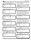
Note: Pressing and holding the RESET TARGETS/RESET
MAX CURRENT key for three seconds will reset the
minimum and maximum Demand values.
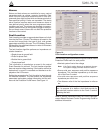
36 Gnd Min ____________A
Time Date
Ph1-2 Min ____________A
Time Date
Screen 36 – Ground Min, Phase 1-2 Min Demand
Currents
Note: Demand currents are a time integrated value and do not
reflect minimum or maximum instantaneous currents.
The demand integration time constant is set via the inter-
face software demand metering screen. These are the
same values displayed in the histogram screen.