


Closing the Recloser During
Testing
Electrical Closing—Solenoid-Operated
Reclosers
Line voltage is required for automatic recloser operation
during testing of reclosers equipped with a closing
solenoid (except for reclosers equipped with the low volt-
age closing accessory).
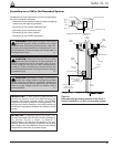
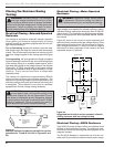
For on-line testing, bypass the recloser, open the load-
side disconnects and keep the source-side disconnects
closed. This will remove the recloser from service, but will
keep line voltage supplied to the closing solenoid (Figure
44).
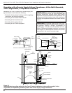
For shop testing, the closing solenoid voltage is supplied
by back-feeding a transformer with a low-side rating equal
to the voltage rating of an available power source, and a
high-side rating equal to the voltage rating of the recloser
(Figure 45). A 75kVA transformer of the proper voltage
rating with an impedance drop of approximately 3% is sat-
isfactory. The ac source must have a comparable
impedance drop.
The closing coil requirement is approximately 200kVA
during the two-to-three cycle closing operation. The
solenoid coil operating voltage must be maintained at the
recloser bushings during the cycle interval the closing coil
is energized. This procedure is not used on reclosers
equipped with the low-voltage closing accessory.
Electrical Closing—Motor-Operated
Reclosers
High-voltage is not required for reclosers utilizing a motor-
operated closing mechanism energized from a 230VAC
power source. For information on energizing the recloser,
refer to the appropriate motor-operated recloser installa-
tion manual.
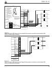
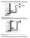
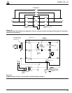
Figure 43 shows a test circuit for motor-operated and
solenoid-closing reclosers with low-voltage closing. Since
these reclosers require only a 240 Vac source for closing,
high-voltage transformer T3 and its protective cage is
eliminated. All other equipment is the same as the test
equipment shown in Figure 42.
Electrical Closing—NOVA Reclosers
Type NOVA 3-phase reclosers utilize an interface circuit
located in the mechanism housing. The electronic inter-
face circuit controls the opening and closing signals to the
magnetic actuator.
The Dc NOVA Recloser is tested with the dc-to-dc con-
verter and 19-pin cable connected to the dc power supply.
Kyle Form 5, Form 5 UDP, Form 5 DC NOVA Recloser Control Installation and Operation Instructions
44
WARNING: Hazardous voltage. Solidly ground
all equipment. Failure to comply can result in
death, severe personal injury, and equipment damage.
T223.2
!
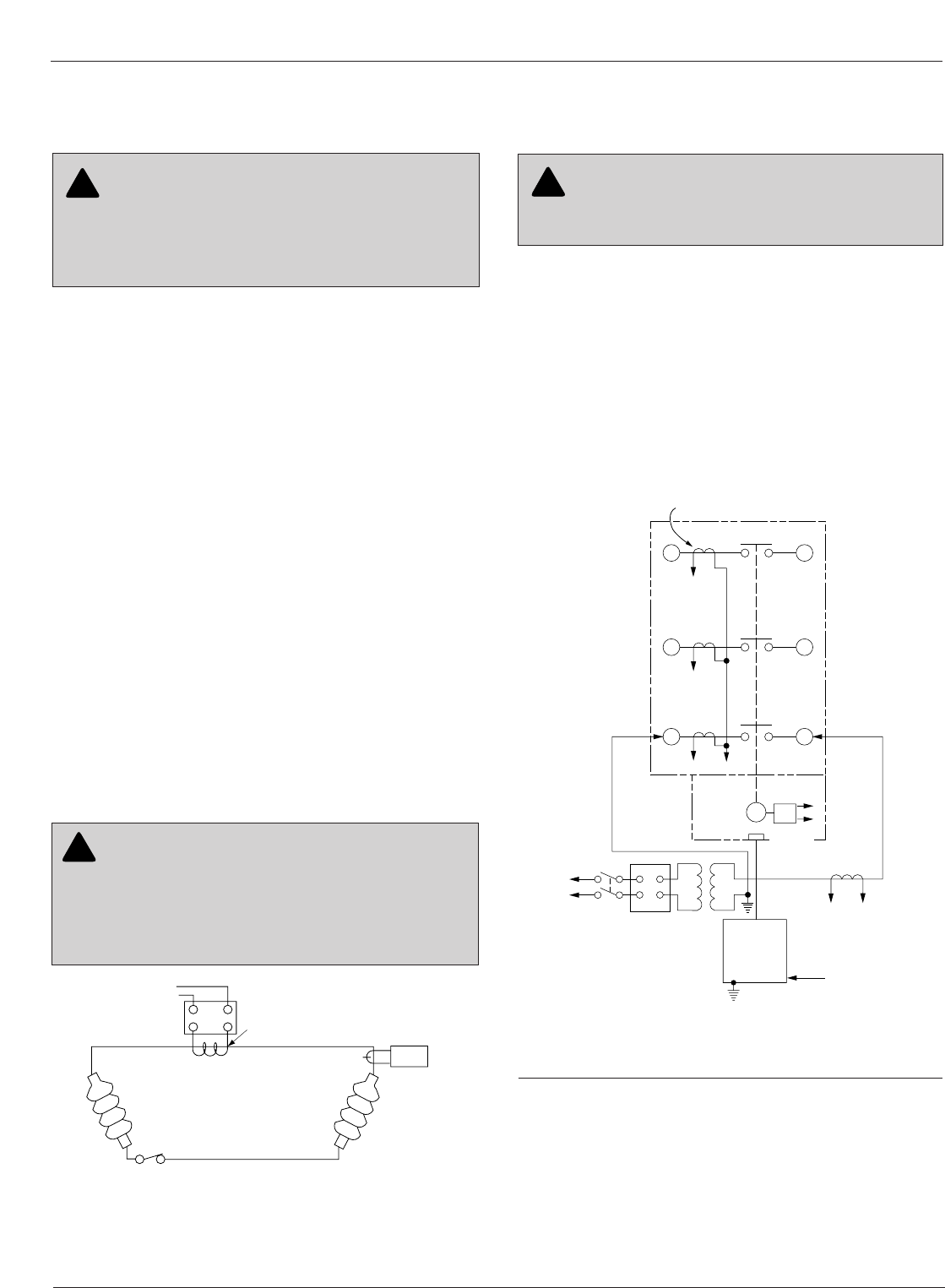
Figure 43.
Suggested test circuit for motor-operated, solenoid-
closing reclosers with low-voltage closing.
65
43
21
Electronic
Control
J
GK
H
XW
240 Vac
Power
Supply
Closing
Motor
T1 T2
240 Vac
Variable
Autotransformer
240 Vac-20 A
120 Vac
To Ammeter
and Relay
to operate
cycle counter or
other timing
device
Sensing CTs (3)
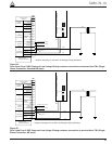
WARNING: Hazardous voltage. Interconnect
source leads X and Y and ground solidly to the
recloser tank (Figure 45). Do not connect lead Z to any
other phase or mechanical ground. Dangerous voltages
to ground exist on the phase connected to lead Z. Solidly
ground all equipment. Failure to comply can result in
severe personal injury and/or equipment damage. T224.1
!
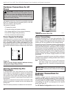
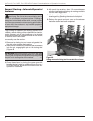
Figure 42.
Alternate method of producing variable line current
(substitute for T2 and W-X circuit in Figures 43 and
45).
600:5
Recloser
BCT ON 600:5 Tap
Note: This test circuit
can apply over
800 Amps to the
recloser.
Note: Use at least 2/0
cable between
bushings.
2
1
115Vac
Variable
Autotransformer
(10 Amp)
Clamp-On
Ammeter
WARNING: Hazardous voltage. The switchgear
and high voltage transformer must be in a test
cage or similar protective device to prevent accidental
contact with the high voltage parts. Solidly ground all
equipment. Failure to comply can result in death,
severe personal injury, and equipment damage. T221.3
!