


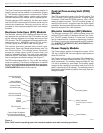

RS-232 Communication Port
The standard Form 5 control is equipped with a operator
panel RS-232 port for interface with a personal computer
running the Form 5 interface software program. This nine-
pin female data communication equipment (DCE) Port 1
permits the uploading of all programming information
stored in the control, including protection profiles, event
recorder, data profiles, alarms, counters, and metering
information. Port 1 provides a simple means to download
operating parameters from a personal computer to the
control.The protocol, baud rate and address for Port 1 are
identified from the LCD display.
If a fiber-optic or RS-232 accessory board is connected to
Port 2 (located on the back of the operator panel) any
external electrical connection from the operator panel will
disable the accessory board.
Note: The operator panel RS-232 port is intended only for
temporary connection of a personal computer. Perma-
nent serial communications must be made via the RS-
232 or fiber-optic accessory board.
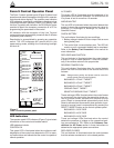
Battery Test Procedure
The condition of the control battery is tested by depress-
ing the BATTERY TEST hot key on the operator panel. No
external current/voltage meter is necessary for testing.
The control performs a self-test every 12 hours or when
initiated by an external command. When a battery test is
initiated, the spurious charge is first drained to allow the
battery voltage to equalize. A 10-ohm, 55-watt resistor is
then placed across the battery terminals and a voltage
drop is calculated. If the drop from the equalized voltage
to the test voltage exceeds 2 volts, then the CHECK BAT-
TERY LED is illuminated.
To perform a battery test:
1. Using the Next and BACK keys, scroll through the
LCD display to Screen 31, the Battery Monitor screen.
2. Record the NORMAL VOLTS and NORMAL CUR-
RENT readings from the screen.
Note: Voltage should be between 25 to 31 volts with
higher readings at colder temperatures. Under nor-
mal conditions with ac connected and the battery
trickle charging, the current should read less than
20 mA. With ac connected and in bulk charging
mode, current will range from 12 to 600 mA. With ac
disconnected and the battery supplying the load,
current will read -180 mA to -600mA depending on
accessories connected.
3. Momentarily, press the CHANGE/LAMP TEST key,
then BATTERY TEST key.
Note: AC power can be either connected or disconnected
for Step 3.
4. Record the TEST VOLTS reading from the LCD and
the status of the CHECK BATTERY LED. Service the
battery if the CHECK BATTERY LED is illuminated.
Control Features
The Form 5 recloser control offers numerous standard
features and accessories that allow the user the utmost
flexibility in designing a control suitable for their applica-
tion requirements.
Under/Over Frequency Loadshedding
The Form 5 control includes provisions for frequency
loadshedding that trips the recloser for conditions of under
or over system frequency. Access to this feature is
through frequency threshold, trip time, and allowable volt-
age threshold.
With the auto-restoration feature, the Form 5 can be set to
close the recloser after the system frequency and voltage
have recovered. Parameters available for setting include
frequency and voltage thresholds and time delay.
A frequency alarm is available and can be configured for
notification.
Voltage Protection (120 Vac-based)
Voltage protection functionality is included as standard on
all Form 5 controls. A recloser trip will be issued for under
and over voltage conditions when the monitored voltage
falls outside user-specified limits for a selectable time.
Response mode includes any single-phase, all three
phases, and single-phase with three-phase inhibit.
Response mode facilitates protecting against a single
phase condition common when a high side fuse operates
on a distribution transformer. Parameters are also avail-
able to provide auto restoration after a trip. A voltage
alarm is available and can be configured for notification.
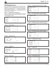
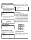
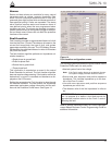
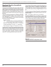
Protection Profiles
Four separate protection profiles are included to allow the
user to adapt overcurrent settings for varying system con-
ditions such as load, live line work or weather. The active
profile is selected from the operator panel or with the inter-
face software or SCADA (Figure 9). Each profile has 14
TCC specifications plus reclose intervals, sequence coor-
dination and reset times to maintain independent protec-
tion parameters.
Kyle Form 5, Form 5 UDP, Form 5 DC NOVA Recloser Control Installation and Operation Instructions
14
Figure 9.
Interface software sample protection profile.