


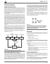

Power Metering
Power metering includes single- and three-phase Watts,
VARS, KVARS, KWH measurements, and the per phase
and total system Power Factor (PF).
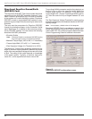
Power Factor Sign Metering
This feature allows a user to configure the sign that is
applied to the power factor. The user may select between
the standard definition of power factor (cosine of angle
between current and voltage) or the Cooper Power Sys-
tems default of the power factor sign following power flow.
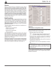
Voltage Metering
Six voltages (3-source and 3-load) are metered as stan-
dard on the Form 5 control. The user selects either phase-
to-phase or phase-to-ground values from the control
operator panel, interface software, or serial communica-
tions. This reference is changed by selecting the voltage
sensor correction in the “Hardware” setup portion of the
interface software.
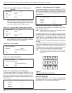
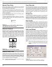
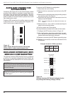
Fast Trips Disabled
Fast Trips Disabled provides the user a quick and effi-
cient method for reducing momentary interruptions or
“blinks”. When activated from the front keypad, pro-
grammed trips to lockout will time according to the
selected time-current curve for Fast Trips Disabled. This
curve is programmable for both phase and ground on
each protection profile. A separate trips-to-lockout setting
is also provided. See Figure 9.
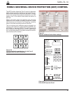
Trip Failure Detection
The Trip Failure Detection feature is an internal diagnos-
tic alarm for verifying the proper operation of circuit trip-
ping and fault clearing of the recloser. Trip Failure
detection indicates the recloser has failed to trip all
phases following a trip signal from the control. Failure to
trip is assumed if a current of at least 10 Amps is detected
approximately 2 seconds after the trip signal is initiated.
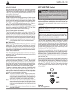
Upon activation of the feature, these four LEDs flash 1
second on, 1 second off (Figure 10):
• RECLOSER MALFUNCTION
• RECLOSER CLOSED
• RECLOSER OPEN
• CONTROL LOCKOUT
The Trip Failure Detection alarm may be triggered from
many potential sources including mechanical, electrical,
control, or interrupter failure. Interrupter failure may
include loss of vacuum in a vacuum interrupter.
To clear Trip Failure Alarm, depress and hold the RESET
TARGETS/RESET MAX CURRENTS keypad for 3 sec-
onds. This also resets targets and demand currents.
Note: There is no remote reset available with the trip failure
detection feature. It cannot be remotely turned off.
When the trip failure alarm is activated, an event is
recorded and a status alarm activated (if enabled) and
preserved during system resets.
To test the Trip Failure Detection feature, see Testing
With Type MET Tester in the TESTING AND TROU-
BLESHOOTING section of this manual.
S280-79-10
15
!
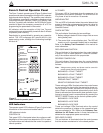
SAFETY
FOR LIFE
AC POWER
ABOVE MIN TRIP
REVERSE POWER FLOW
RECLOSER MALFUNCTION
CHECK BATTERY
BUSHINGS 1-2 FAULT TARGET
BUSHINGS 3-4 FAULT TARGET
BUSHINGS 5-6 FAULT TARGET
GROUND FAULT TARGET
SENSITIVE-GROUND FAULT TARGET
BUSHINGS 1-2 VOLTAGE
BUSHINGS 3-4 VOLTAGE
BUSHINGS 5-6 VOLTAGE
RECLOSER CLOSED
RECLOSER OPEN
CONTROL LOCKOUT
Figure 10.
RECLOSER MALFUNCTION, RECLOSER CLOSED,
RECLOSER OPEN and CONTROL LOCKOUT LEDs
will blink for the affected phase as indication of Trip
Failure.
DANGER: Explosion. Stay clear of a recloser
that is in a trip failure mode. A recloser in trip fail-
ure mode may explode resulting in death or severe per-
sonal injury. T271.0
!
IMPORTANT: The recloser must be isolated and de-
energized immediately upon detection of trip failure.
Follow proper procedures and safety practices to iso-
late and de-energize the recloser.
WARNING: Hazardous voltage. This device is
not a substitute for a visible disconnect. Follow all
locally approved safety practices. Failure to follow
proper safety practices can result in contact with high
voltage, which will cause death or severe personal
injury.
G112.1
!