


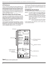
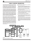
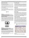
Form 5 Control Operator Panel
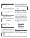
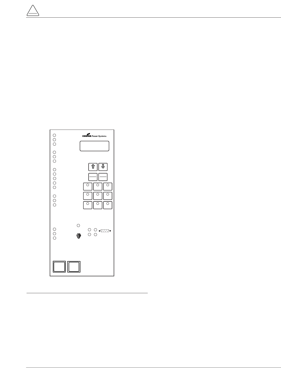
The Form 5 control operator panel (Figure 8) allows local
operation and status interrogation through built-in operator
controls and status displays. The operator panel contains
LED indicators, operational pushbuttons, membrane-type
functional/indication switches, backlit LCD display, and
Hot Line Tag switch with indication. An RS-232 port is also
provided to permit the temporary connection of a PC for
programming the parameters in the control.
All indicators with the exception of Hot Line Tag and
recloser status are automatically turned off after 5 minutes
of operator panel inactivity.
Reactivating is accomplished by pressing any operation
switch. The LCD messages will remain while in this
power-saving mode, although the illuminating backlight
will shut off.
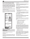
LED Indicators
The operator panel LED indicators (Figure 5) give instant
information on the control and recloser status.
LED indicators include:
CONTROL OK
This green LED is illuminated when the continuous self-
diagnostics of the control have detected no CPU or mem-
ory malfunctions and indicate that the control is capable of
normal operation.
AC POWER
This green LED is illuminated when the presence of ac
input power to the control is sensed. The LED will turn off
if ac power is lost for more than 10 seconds.
ABOVE MIN TRIP
This red LED is illuminated when the control detects that
current is above the programmed minimum trip value for
Bushings 1-2, Bushings 3-4, Bushings 5-6, Ground, or
Sensitive Ground.
CHECK BATTERY
This red indicator illuminates for two conditions:
1. Battery voltage is below 20 Vdc or drops 2Vdc or more
during battery test.
2. The control fails a manual battery test. The LED will
remain on until a successful battery test is completed.
Refer to the Battery Test Procedure in this manual for
more information.
RECLOSER MALFUNCTION
This red indicator is illuminated when the control detects
a failure in a trip or close operation. It turns off automati-
cally if the recloser returns to the proper state.
REVERSE POWER FLOW
This red indicator illuminates when the control detects
power flow from the load side to the source side of the
recloser.
Note: Voltage sensor polarity and phase must be correct for
reverse power flow to function properly.
BUSHINGS 1-2 FAULT TARGET
BUSHINGS 3-4 FAULT TARGET
BUSHINGS 5-6 FAULT TARGET
GROUND FAULT TARGET
SENSITIVE GROUND FAULT TARGET
These red target LEDs illuminate when the control issues
an overcurrent trip signal while the respective phase cur-
rent or ground current exceeds the minimum pickup
value. Reset is accomplished automatically when Auto
Reset is activated and a successful close operation is per-
formed or manual reset is accomplished by pressing the
RESET TARGETS button on the control operator panel.
BUSHINGS 1-2 VOLTAGE
BUSHINGS 3-4 VOLTAGE
BUSHINGS 5-6 VOLTAGE
These red voltage LEDs illuminate when the control
detects the presence of voltage on the respective bush-
ings as connected to TB1. Refer to the Customer Con-
nections for AC Power section in these instructions to
determine the appropriate power connections.
RECLOSER CLOSED
This red indicator is illuminated when the control senses
that the recloser mechanism is in the closed position.
S280-79-10
7
!
SAFETY
FOR LIFE
Figure 5.
Form 5 control operator panel.
CONTROL OK
AC POWER
ABOVE MIN TRIP
REVERSE POWER FLOW
RECLOSER MALFUNCTION
CHECK BATTERY
BUSHINGS 1-2 FAULT TARGET
BUSHINGS 3-4 FAULT TARGET
BUSHINGS 5-6 FAULT TARGET
GROUND FAULT TARGET
SENSITIVE-GROUND FAULT TARGET
BUSHINGS 1-2 VOLTAGE
BUSHINGS 3-4 VOLTAGE
BUSHINGS 5-6 VOLTAGE
RECLOSER CLOSED
RECLOSER OPEN
CONTROL LOCKOUT
BACK
NEXT
LAMP
TEST
CHANGE
RESET
TARGETS
RESET
MAX CURRENT
GND TRIP
BLOCKED
NON
RECLOSING
SUPERVISORY
BLOCKED
COLD LOAD
PICK UP
BLOCKED
BATTERY
TEST
FAST
TRIPS
DISABLED
ALTERNATE
PROFILE
NO. 1
ALTERNATE
PROFILE
NO. 2
ALTERNATE
PROFILE
NO. 3
HOT LINE
TAG
ON
OFF
TX 3
RX 3
CLOSE
TRIP
(LOCKOUT)
KYLE
®
FORM 5
RECLOSER CONTROL
RS232
TX 2
RX 2