


Communications
Communication Ports
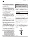
The Form 5 control has three communication ports from
the CPU module. Two of the three ports are user-acces-
sible. Communication Port 1 is the operator panel LCD
display where data is exchanged between the CPU and
the operator panel. Though not user-configurable, Port 1
allows for flexible modifications to the front panel for cus-
tom applications.
The operator panel RS-232 communication Port 2 pro-
vides temporary local personal computer (PC) access
when connected with a standard 9-pin cable. Port 2 pro-
vides a dual communication interface for the user. The
port includes a software switch for two external connec-
tions; the operator panel RS-232 DB-9 connector, or the
fiber-optic/RS-232 communication accessories. Local
connection to the operator panel RS-232 connection
takes precedence over the communication accessory.
Disconnecting the operator panel RS-232 communication
automatically reconnects the communication accessory
to Port 2.
Accessory Ports 2 and 3 are resident on the back of the
operator panel and can be configured to either 2179 or
DNP3.0 protocols. Port 3 provides uninterrupted commu-
nication to the RS-232 or Fiber-Optic accessory, and is
not affected by any other port or physical connection.
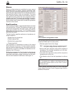
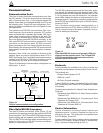
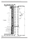
Figure 16 illustrates the communication configuration for
serial ports1, 2, and 3.
Fiber-Optic/RS-232 Accessory
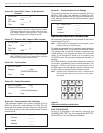
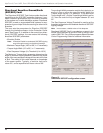
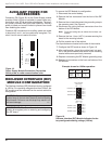
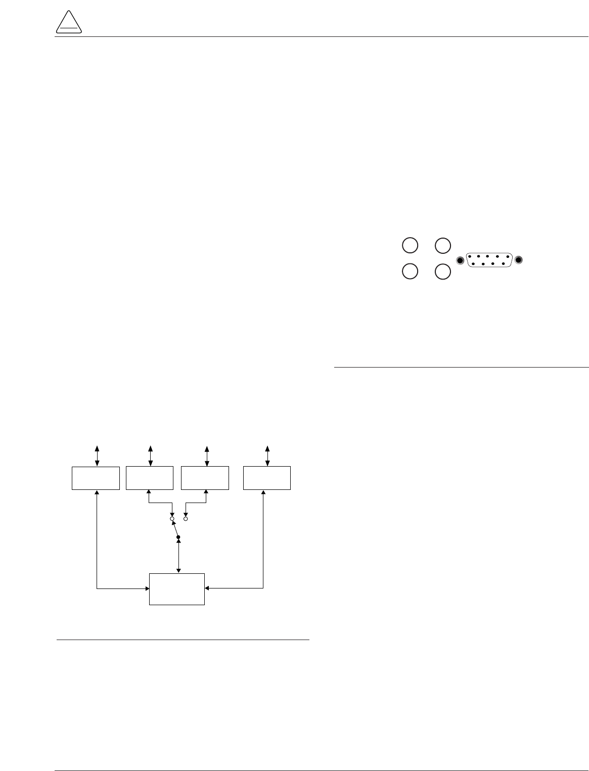
Two sets of receive and transmit LEDs (Figure 17) are
provided on the operator panel for fiber-optic and RS-232
communications. The TX2 and RX2 LEDs illuminate when
communicating with the operator panel RS-232 port. The
TX3 and RX3 LEDs illuminate when communicating with
either the fiber-optic or RS-232 interface accessory
boards on communication Port 3.
The RS-232 accessory board and the fiber-optic acces-
sory boards are located behind the operator panel. Each
accessory board can be connected to either Port 2 or Port
3; no two boards can use the same port. The operator
panel LEDs indicate the status of communication on the
accessory boards. Temporary connections to the operator
panel RS-232 port disables fiber-optic or RS-232 commu-
nication at Port 2.
Port 3 provides uninterrupted communication to a
remote terminal unit (RTU). Refer to S280-79-4 Form 5
Serial communications Accessory Operation Instruc-
tions for additional information.
Protocols
Three protocols are available for the Form 5 control and
are factory-configurable to communication Ports 2 and 3.
The protocols are:
• Cooper Power Systems 2179
• DNP3.0, Level 3
• S-Comm Protocol accessory
Protocol DNP3.0 includes “Unsolicited Report by Excep-
tion” functionality and Protocol 2179 includes 2-bit status
functionality.
Complete documentation for Cooper Power Systems pro-
tocols are:
• Reference Data R280-90-12, Serial Communication
Protocol 2179
• Reference Data R280-90-13, Communication Point
Database for Protocol 2179
• Reference Date R280-90-14, Communication Point
Database for Protocol DNP3.0
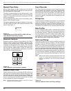
Control Information
Control information, including firmware version and
database version, is factory installed and can not be
altered by the user. This information is accessible from
the LCD display, Screen 39.
Communication Ports 2 and 3 settings can be referenced
from the LCD display, Screens 40 and 41 respectively.
(Port 1 shares the same settings as Port 2.)
S280-79-10
19
!
SAFETY
FOR LIFE
COMMUNICATIONS
PORT 1
(Internal Use Only)
COMMUNICATIONS
PORT 2
(Shared)
(Metering, Histograms
Profiles, Alarms, Targets)
CPU
TEMPORARY
ENGINEERING
(Local PC)
OPERATOR PANEL
DISPLAY AND
KEYPAD
OPERATIONS
OPERATOR
PANEL
RS-232
ENGINEERING
(Radio, Fiber-Optic, Modem)
RS-232 or
FIBER-OPTIC
ACCY
RS-232 or
FIBER-OPTIC
ACCY
SCADA SYSYEM
(Radio, Fiber-Optic, Modem)
COMMUNICATIONS
PORT 3
(Dedicated)
AUTO TRANSFER
SWITCH
(Operator Panel
Connection Disables
Accessory)
Figure 16.
Control communication port configuration.
TX 2
RX 2
TX 3
RX 3
RS232
Figure 17.
Fiber-Optic/RS-232 receive and transmit LEDs and
data port on the operator panel. The TX2 and RX2
LEDs illuminate during communication with the
operator panel RS-232 port.