


S280-79-10
39
!
SAFETY
FOR LIFE
TB1
Y' VOLTAGE
120Vac
B' VOLTAGE
120Vac
CLOSING
VOLTAGE
NEUTRAL
SOURCE 2
NEUTRAL
SOURCE 1
AC
CUSTOMER
CONNECTIONS
NEUTRAL
ZØ
YØ
SOURCE 2
POWER
XØ
OUTPUT
VOLTAGE
NEUTRAL
*NEUTRAL
POWER
SOURCE
OUTPUT
CØ
*BØ
AØ
AC
CUSTOMER
CONNECTIONS
SOURCE 1
POWER
*REQUIRED FOR
CONTROL OPERATION
1
2
3
4
5
6
7
8
9
10
11
12
13
14
240Vac CLOSING
OPTION
NEU
CØ
BØ
AØ
15
16
AØ
BØ
CØ
NEU (LV Closing Output)
HOT (LV Closing Output)
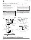
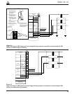
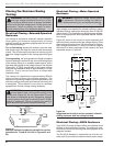
Figure 34.
Form 5 and Form 5 UDP Power and Low Voltage Closing customer connections to terminal block TB1
(120Vac or 240Vac Wye Connection).
AC
CUSTOMER
CONNECTIONS
ZØ
YØ
XØ
SOURCE 2
POWER
OUTPUT
VOLTAGE
OUTPUT
VOLTAGE
*CØ
POWER
SOURCE
OUTPUT
BØ
*AØ
AC
CUSTOMER
CONNECTIONS
SOURCE 1
POWER
*REQUIRED FOR
CONTROL OPERATION
SEE POWER SUPPLY
MODULE FOR
CORRECT VOLTAGE
TB1
1
2
3
4
5
6
7
8
9
10
11
12
13
14
CØ
BØ
AØ
240V CLOSING
OPTION
15
16
AØ
BØ
CØ
HOT (LV Closing Output)
HOT (LV Closing Output)
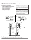
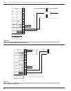
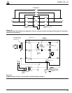
Figure 35.
Form 5 and Form 5 UDP Power and Low Voltage Closing customer connections to terminal block TB1
(120Vac or 240Vac Delta Connection).
TB1
16
15
14
13
12
11
10
9
8
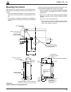
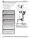
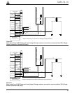
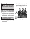
1. Insert 3/32 inch flat-
blade screwdriver into
Wire Release and
Locking hole.
2. Carefully insert the
screwdriver along side
the locking clamp.
3. Pull toward the center
of terminal block TB1
until the locking clamp
opens.
4. Insert wire into Terminal
Connection hole.
5. Release screwdriver.
6. Carefully pull wire to be
sure it is secure.
To insert wire:
Terminal
Connection Hole
3/32 inch
Flat-Blade
Screwdriver
TB1
(Top View)
Connection
Wire
Wire Release
and Locking Hole
Note: Only slight pressure is
required to open the
locking clamp. Excessive
pressure can damage
the terminal block.