


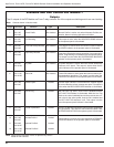

Initial Programming
Prior to Installation
The control must be programmed with all necessary oper-
ating settings, all alternate profiles, and parameters prior
to operation with an energized recloser.
Note: Program all protection profiles. Unused alternate pro-
files should be programmed with the same settings as
one of the applicable profiles. Default settings on
unused alternate profiles can cause unnecessary out-
ages if they are below normal system requirements.
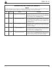
Initial programming of the control is the responsibility of a
qualified technician or engineer familiar with control func-
tions and programming parameters required for the spe-
cific recloser installation.
The control must be programmed with the Form 5 inter-
face software.
Control / Recloser Compatibility
Reclosers manufactured prior to June 1989 are equipped
with Type A bushing current transformers. These
reclosers were designed for use with Form 2, Form 3, and
Form 3A controls. Because the Form 5 control is designed
for use with reclosers equipped with Type B current-sens-
ing Transformers, reclosers retrofitted with Form 5 con-
trols should be retrofitted with Type B current
transformers. All reclosers manufactured since 1989 are
equipped with Type B (1000:1, 1000/500:1, or 2000:1)
sensing CTs.
Reclosers equipped with Type B sensing CTs are com-
patible with all Kyle recloser controls (Form 2, Form 3,
Form 3A, Form 4A, Form 4C, FXA, FXB and Form 5, Form
5 LS/UDP controls), and are identified with the following
label prominently displayed on the recloser sleet hood or
the front of the operator cabinet:
The Form 5 control can be used with the old-style Type A
CTs; however, the event recorder, data profiler and duty
cycle monitor will have limited accuracy for currents
above 5000 Amps.
Retrofit kits with the new Type B sensing CTs are avail-
able to upgrade existing families of reclosers for operation
with Form 5 controls. For additional information, contact
your Cooper Power Systems representative.
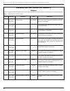
For identification, Table 4 lists the serial number breaks
between old-style Type A and the new-style Type B sens-
ing CTs. Below this serial number, the recloser is
equipped with the Type A CTs.
Note: For reclosers shipped prior to June 1989 and not listed
below, please contact your Cooper Power Systems rep-
resentative with the recloser type and serial number for
verification of Type A or B bushing current transformers.
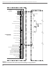
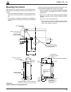
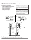
Control Cable
The control cable is fabricated with connectors which
mate with the female receptacle of the recloser on one
end and the male receptacle of the control on the other
end.
Note: The control cable must be supported along its length to
prevent repeated movement due to wind or other out-
side forces which can damage the cable.
Kyle Form 5, Form 5 UDP, Form 5 DC NOVA Recloser Control Installation and Operation Instructions
32
TABLE 4
Serial Number Break for Reclosers with Type A
Sensing CTs
Recloser Below Serial Number
RXE 5831
RVE 5894
WE 11199
WVE 3695
VWE 7199
VWVE27 7208
VWVE38 1204
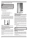
NOTICE
RECLOSER IS EQUIPPED WITH
TYPE B SENSING CTs.
RECLOSER DOES NOT HAVE A
BATTERY CHARGER.
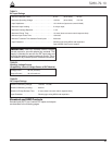
INSTALLATION PROCEDURE
CAUTION: Equipment Misoperation. Do not
connect this control to an energized recloser until
all control settings have been properly programmed
and verified. Refer to the programming information for
this control. Failure to comply can result in control and
recloser misoperation, equipment damage, and per-
sonal injury. G110.3
!
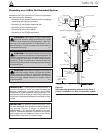
WARNING: Hazardous voltage. Recloser and
control must be solidly grounded. Follow all locally
approved procedures and safety practices when
grounding this equipment. Improper grounding can
result in contact with high voltage, which will cause
death or severe personal injury. G115.1
!
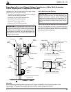
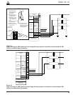
IMPORTANT: All external inputs to the Form 5 con-
trol must be routed within 8 inches of their correspond-
ing ground. During a surge, a potential of
approximately 1.5 kV per foot can develop in the con-
ductors. Differences between conductor and ground
path lengths can add additional stress to the control
components in the event of a power surge.