


Introduction
Service Information S280-79-10 provides installation and
operation instructions for the Kyle Form 5 and Form 5
UDP microprocessor-based electronic recloser controls.
Read This Manual First
Read and understand the contents of this manual and fol-
low all locally approved procedures and safety practices
before installing or operating this equipment.
Additional Information
These instructions cannot cover all details or variations in
the equipment, procedures, or process described, nor
provide directions for meeting every possible contingency
during installation, operation, or maintenance. When
additional information is desired to satisfy a problem not
covered sufficiently for the user's purpose, please contact
your Cooper Power Systems sales representative.
ANSI Standards
Kyle reclosers are designed and tested in accordance
with the following ANSI standards: C37.60 and C37.85
and ANSI Guide C37.61.
Quality Standards
ISO 9001:2000-Certified Quality Management System
Acceptance and
Initial Inspection
Each Form 5 control is completely assembled, tested, and
inspected at the factory. It is carefully calibrated, adjusted
and in good condition when accepted by the carrier for
shipment.
Upon receipt, inspect the carton for signs of damage.
Unpack the control and inspect it thoroughly for damage
incurred during shipment. If damage is discovered, file a
claim with the carrier immediately.
Handling and Storage
Be careful during handling and storage of the control to min-
imize the possibility of damage. If the control is to be stored
for any length of time prior to installation, provide a clean,
dry storage area. If storage is in a humid atmosphere, make
provisions to keep the control circuitry energized.
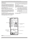
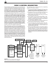
Note: To energize the control, apply AC power to the AC sup-
ply input connector block TB1 located left of the
Recloser Interface (RIF) module within the control.
Refer to the Customer Connection for AC power sec-
tion in this manual.
Control Battery Storage and Charging
The 24 Vdc control battery in the Form 5 control is fully
charged prior to shipment and is ready for use. In order to
maintain sufficient charge to operate the control, the
sealed lead acid battery should be charged after no more
than three months of storage.
Note: Two 12 Vdc, 13 amp-hour batteries are available for
use with the Form 5 Distribution Automation upgrade
accessory.
Temperature has an effect on battery life. Sealed lead
acid batteries should be stored, fully charged, at room
temperature. Never store lead acid batteries at tempera-
ture exceeding 47°C (117°F), as damage can result in
approximately one month.
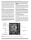
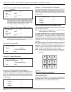
To keep the battery charged, energize the control’s built-
in charger with AC power applied to the user AC supply
input connector block TB1, located left of the RIF module
within the control cabinet.
Note: When shipped from the factory, the battery source is
disconnected and its output plugs are taped to the cab-
inet. Connect the battery plugs into the mating connec-
tors to complete the battery circuit.
Battery Replacement
The 24 Vdc control battery has a life expectancy of 4 to 6
years. It is recommended that the battery be replaced
after 4 years.
Control Power
The primary source of power is factory configured for 120 Vac
or 240 Vac. The 240 Vac version is available as an option
at time of order entry. Primary power is rectified to charge
the power capacitor and to power the dc/dc converter that
provides power to the control. A minimum of 500 mA of ac
current is required for heater operation, battery charging
current, and to keep all modules energized.
S280-79-10
3
!
SAFETY
FOR LIFE
PRODUCT INFORMATION
IMPORTANT: Connect the control battery when AC
power is connected to the control’s AC supply Input Ter-
minal Block. The battery must be disconnected prior to
shipping or storing the control.
IMPORTANT: To maintain sufficient charge to oper-
ate the control and prevent battery cell damage, the
sealed lead-acid batteries should be charged after no
more than three months of storage.