


Customer Connections for AC
Power
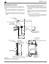
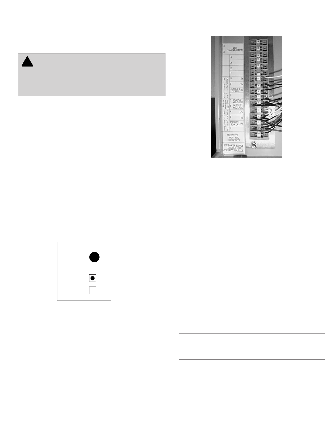
Input power to the Form 5 control is connected to terminal
block TB1 (located behind the operator panel, on the left
side of the control). See Figure 33.
Input power is required:
• To power the control
• To provide voltage and power metering
• For voltage detection for loop scheme accessory
• For the low voltage closing accessory
• For the convenience outlet accessory
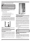
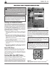
Power Supply Verification
Incoming power is routed to the Power Supply module
which is factory configured for either 120 or 240 volt oper-
ation. The power supply module is factory wired to TB-1
and protected by the 3.15 Amp fuse labeled F2 on the
power supply operator panel. A label on the Power Sup-
ply module indicates the proper voltage rating. See Figure
32.
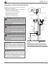
Inserting and Releasing Wire
Connections
In Terminal Block TB1, each terminal has a wire locking
clamp that has to be opened to accept and secure the
wire. A 3/32 inch flat-blade screwdriver is inserted into
each terminal hole to open the locking clamp. Figure 34
provides the procedure for opening and securing the wire
connections.
The wire is inserted into the terminal connection hole
while the screwdriver is placed into the wire release and
locking hole.
Follow the same procedure to release wire connections.
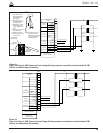
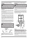
Power Connections
Customer connections to TB1 vary upon application. TB1
connections provide power and metering inputs to the
control. Figures 34 through 39 show the customer con-
nections for 120 Vac and 240 Vac low voltage closing.
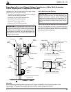
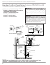
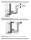
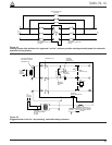
Figures 34 through 37 illustrate customer connections for
single-phase transformers. Figure 34 shows standard
wiring with BØ transformer connected to TB1-2 location.
Other phases should be connected from the single-phase
transformer by wiring the BLACK wire from the Power
Supply module to the terminal of the respective phase as
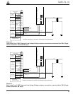
shown in Figure 38 and 39. For example, Figure 39 shows
connection from the Power Supply module to an AØ
transformer.
The transformer required for power should be a minimum
of 5kVA for low-voltage ac closing reclosers and 1kVA for
dc closing reclosers.
Note: An out-of-service Form 5 or Form 5 UDP control (for
either Wye or Delta) can be powered by connecting to
TB1-2 (hot) and TB1-4 (neutral) to an appropriate power
source.
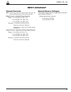
Customer Connections for
Metering
Customer voltage inputs for metering are field config-
urable on the RIF module to accept 12, 120, or 240 Vac.
The incoming power supply must match the indication for
incoming power on the RIF module. The factory-config-
ured settings for the RIF are displayed on the module
panel. See Figure 19.
See RIF Module Configuration section of this manual.
Kyle Form 5, Form 5 UDP, Form 5 DC NOVA Recloser Control Installation and Operation Instructions
38
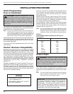
CAUTION: Equipment damage. Do not drill con-
nection holes into the top of the cabinet. Connec-
tion holes in the top of the cabinet will allow moisture to
seep into the control and damage the components or
cause control misoperation. Failure to comply will void
the control’s factory warranty. T249.0
!
Figure 33. 99003KM
Terminal Connector Block TB1.
IMPORTANT: Delta connections are not used on any
Form 5 control accessory that utilizes the low voltage
transfer relay.
Y
M
O
D
U
L
E
CONFIGURED
FOR
120
VAC
240
VAC
F2
GDC-3.15A
Figure 32.
Label on Power Supply module indicates factory-
configured voltage rating (120Vac).