


S280-79-10
23
!
SAFETY
FOR LIFE
DISCRETE INTERFACE (DIF)
ACCESSORY
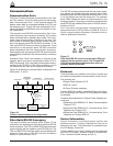
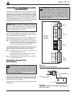
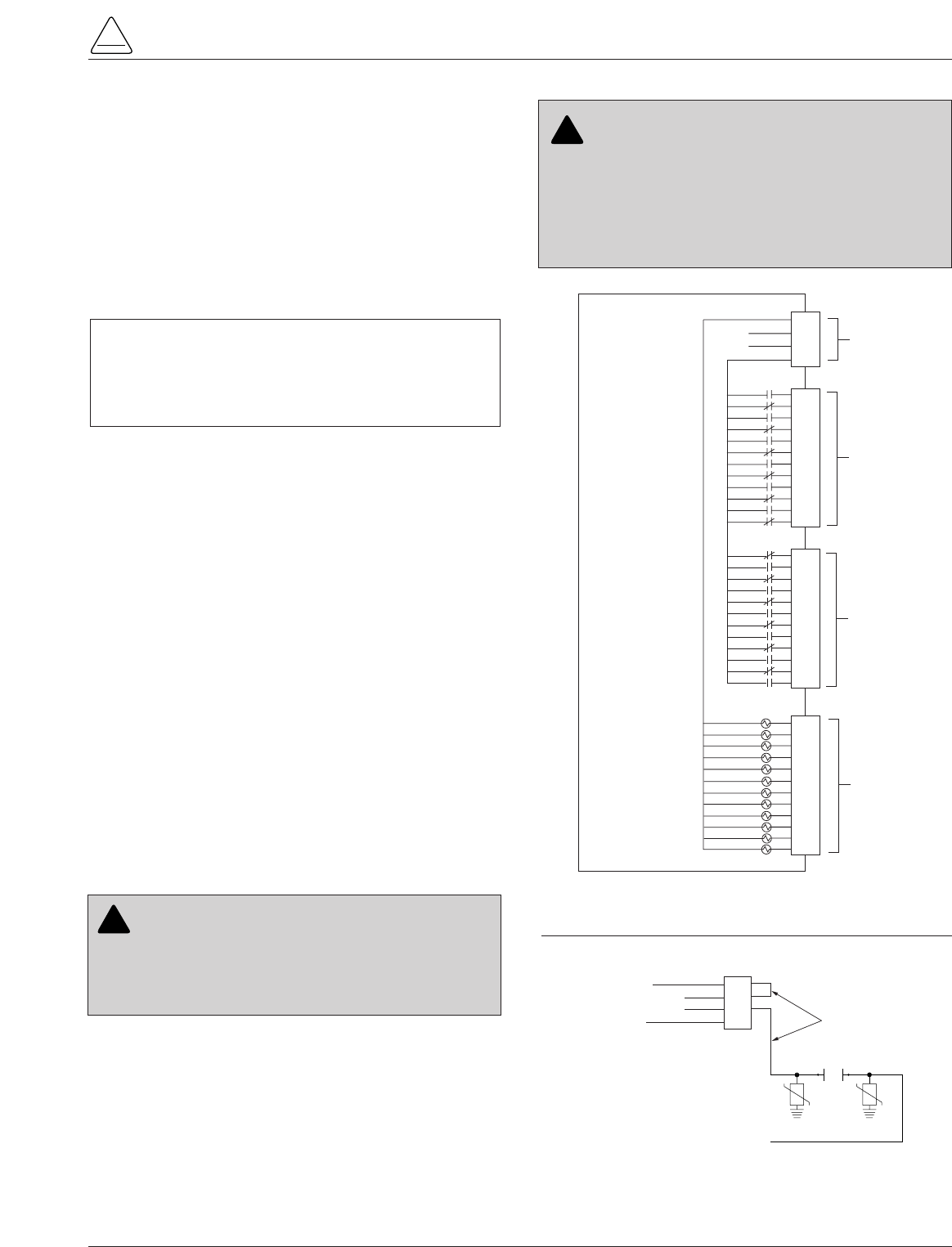
The Discrete Interface (DIF) module accessory (Figure
25) permits connection of contact-type input devices
(switches, relays) and discrete indicating devices (relays,
LEDs, lamps) to the Form 5 control to effect local discrete
input/output (I/O). The DIF module accessory is used for
supplementing normal local controls and status indicators
for discrete SCADA functions. All DIF inputs and outputs
have been factory-set and are shown in Figure 27.
The DIF module contains 12 factory-set inputs and out-
puts for discrete SCADA functions. Each Form 5 control
can accommodate two DIF modules.
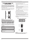
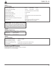
Whetting voltage for the DIF inputs can be supplied by the
DIF module or by the customer as shown in Figure 26.
Note: 28 Vdc (nominal) is provided from the DIF module via
connector P5 for use as whetting voltage for inputs to
P4. As an alternative, the user can supply whetting volt-
age from an auxiliary source, such as a RTU.
The input voltage range is 12 to 120 Vac or Vdc. The 12
outputs are Form C relay contacts. Six of the module out-
puts are latching and the other six are non-latching.
Note: Latching is defined as an output that retains its status
when control power is removed.
Non-latching is defined as an output that changes its
status when control power is removed.
Note: A remote function is not controlled by the SUPERVI-
SORY BLOCKED switch.
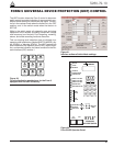
Customer Connection
Information
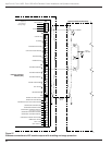
Figure 25 shows the customer-supplied wiring of whetting
voltage for DIF module inputs. Connection is made from
terminal P5 on the DIF module to the respective connec-
tions on P4 inputs 1 through 12.
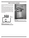
Figure 27 shows customer connections to the DIF outputs
at P2 and P3.
4
3
2
1
4
3
2
1
8
7
6
5
12
11
10
9
6
5
4
3
2
1
4
3
2
1
8
7
6
5
12
11
10
9
12
11
10
9
8
7
4
3
2
1
8
7
6
5
12
11
10
9
INPUT COMMON
28V (–)
28V (+)
OUTPUT COMMON
P5
P3
P2
P4
DISCRETE
INTERFACE
MODULE
ACCESSORY
WHETTING
VOLTAGE
UNLATCHED
OUTPUTS
LATCHED
OUTPUTS
INPUTS
(12 TO 120
VAC OR VDC)
WHETTING
VOLTAGE
4
3
2
1
8
7
6
5
12
11
10
9
Figure 25.
Discrete Interface (DIF) Module.
4
3
2
1
INPUT COMMON
28V (-)
28V (+)
OUTPUT COMMON
To P4
Inputs 1 thru 12
P5
Customer-Supplied
Wiring for Whetting Voltage
REMOTE
CONTACTS
Note: Wiring to P5-2 and P5-3 can be
reversed if necessary.
Figure 26.
Customer connections for supplying whetting volt-
age to DIF inputs.
CAUTION: Equipment damage; misoperation.
External leads must be shielded and the shield
must be grounded at both ends. Terminate each lead
with a 320 Vac, 160 Joules metal oxide varistor (MOV),
or equivalent, at the remote end. Attach MOVs between
the leads and ground. Failure to properly shield and
protect leads can result in equipment damage and/or
unintentional operation. G117.3
!
CAUTION: Equipment damage. Do not drill con-
nection holes into the top of the cabinet. Connec-
tion holes in the top of the cabinet will allow moisture to
seep into the control and damage the components or
cause control misoperation. Failure to comply will void
the control’s factory warranty. T249.0
!
IMPORTANT: Do not use DIF module for overcurrent
protection. Digital SCADA can be used for this applica-
tion. The control gives priority to TCC timing and issu-
ing a trip signal rather than changing the status of a DIF
output or responding to a DIF input.