


AUXILIARY POWER FOR
ACCESSORIES
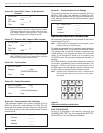
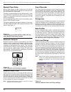
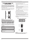
Connection P9 (Figure 18) on the Power Supply module
provides 24Vdc (12Vdc is available) to power radio com-
munication units, RTUs and other accessories. The auxil-
iary power provides 40W peak load capability. Auxiliary
power is fused and current-limited to prevent user loads
from disabling the control.
Customer 28V connections for auxiliary power are made
to terminals 3 and 1 and are continually energized. Ter-
minal 2 and 4 are not used at this time.
RECLOSER INTERFACE (RIF)
MODULE CONFIGURATION
The Recloser Interface (RIF) Module is factory-configured
at 120Vac. For operating voltages other than 120Vac, the
RIF module must be removed from the control cabinet for
configuration.
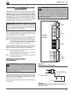
To remove the RIF Module for configuration:
1. Disconnect the control battery.
2. Remove the four connectors from the front of the RIF
Module.
3. Remove the nut and disconnect the grounding strap to
the operator panel. See Figure 4.
4. Disconnect the wiring harness connectors from the
bottom of the RIF Module.
Note: Press the locking tabs to release the harness con-
nectors.
5. Remove the four 11mm (.437 in) screws securing the
board to the mounting bracket.
6. Pull the module out of the cabinet.
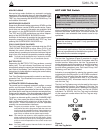
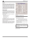
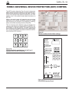
The dip switches are located on the side of the module.
7. Configure the RIF board as shown in Figure 19.
8. After configuration, place the module back into posi-
tion in the control cabinet and secure to the mounting
bracket with screws previously removed.
9. Replace nut securing the RIF Module grounding strap
10. Replace all connectors on the front and bottom of the
RIF Module.
Kyle Form 5, Form 5 UDP, Form 5 DC NOVA Recloser Control Installation and Operation Instructions
20
CAUTION: Equipment damage. Always wear a ground-
ing wrist strap to control static electricity before handling
circuit boards. Failure to use this strap may result in cir-
cuit board damage. T253.1
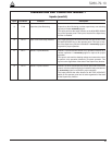
INPUT VOLTAGE
SELECTION
INPUT VOLTAGE
SELECTION
POLE 2
POLE 1
POLE 2
POLE 1
S7
S8
POLE 1
POLE 2
POLE 2
POLE 1
POLE 2
POLE 1
POLE 1
POLE 2
S7
BUSHING 2 (XØ)
BUSHING 4 (YØ)
BUSHING 6 (ZØ)
BUSHING 1 (AØ)
BUSHING 3 (BØ)
BUSHING 5 (CØ)
OFF
ON
OFF
ON
SENSOR
VOLTAGE POLE1 POLE2
12Vac OFF OFF
120Vac* OFF ON
240Vac ON ON
Example shown for 120Vac operation:
*120Vac is factory-set configuration
Figure 19.
Recloser Interface (RIF) Module indicates the fac-
tory-configured metering voltage (120Vac).
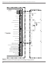
P
O
W
E
R
S
U
P
P
L
Y
P
9
A
U
X
F1
GDC-1A
P
8
C
P
U
SW (-) 4
28V (-) 3
SW (+) 2
28V (+) 1
Figure 18.
Power Supply Module Connection P9 provides
24Vdc power to radio communication units.
IMPORTANT: The Form 5 control must be com-
pletely de-energized prior to removing and configuring
the RIF board.