


RECLOSER OPEN
This green indicator is illuminated when the control senses
that the recloser mechanism is in the open position.
CONTROL LOCKOUT
This green indicator is illuminated when the recloser is
open and a reclosing sequence is not in progress or when
the lockout handle on the recloser mechanism is in the
down position; i.e., trip and close circuits are open.
Note: The RECLOSER MALFUNCTION, RECLOSER OPEN,
RECLOSER CLOSED, and RECLOSER LOCKOUT
LEDs will flash upon detection of a trip failure. See the
Control Features section of this manual.
TRIP (Lockout) Pushbutton
The TRIP pushbutton (Figure 2) provides front-panel
access to trip (lockout) the recloser. When pressed, the
TRIP push-button opens the recloser and locks out the
control.
CLOSE Pushbutton
When pressed, the CLOSE pushbutton (Figure 2) returns
the control to the initial or home position, closing the
recloser. The control is ready for the start of a new
trip/close sequence.
Note: Pressing the CLOSE pushbutton from the Lockout posi-
tion, will initiate Cold Load Pickup (CLPU) protection, if
the feature is first enabled from the interface software
Protection Profile screen, and the COLD LOAD PICKUP
BLOCKED LED on the operator panel is not lit.
If the recloser is closed, pushing the CLOSE pushbutton
has no effect on the control. Depressing and holding the
CLOSE pushbutton does not activate the Cold Load
Pickup feature. See Cold Load Pickup in the Control
Features section of this manual.
The Form 5 control has a Manual Close Delay feature that
provides an interval of time from when the CLOSE push-
button is depressed to the time when manual close oper-
ation is performed. See Manual Close Delay in the
Control Features section of this manual.
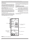
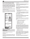
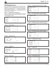
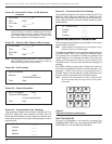
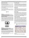
LCD Display
The control operator panel has a large, backlit LCD dis-
play (Figure 6) used for viewing control parameters and
monitoring system conditions. Data is organized into
screens of information, with each display containing four
lines of information, with up to 20 characters per line.
Access to the screens is obtained through navigational
keys which permit the user to scroll through the menu in a
timely and efficient manner.
When an overcurrent trip occurs, the control automatically
displays the fault current values as shown on the LCD dis-
play as Screen 1. Refer to LCD Display Screens section
of this manual.
NEXT Key
Pressing the NEXT key causes the LCD display to scroll to
the next screen of available information. Pressing and hold-
ing the NEXT key causes the control to scroll to subsequent
screens at the rate of about two screens per second.
BACK Key
Pressing the BACK key causes the LCD display to scroll
to the previous screen of available information. Pressing
and holding the BACK key causes the control to scroll to
previous screen.
RESET TARGETS/RESET MAX
CURRENT Key
Pressing the RESET TARGETS/RESET MAX CURRENT
key resets the fault target indicators on the control opera-
tor panel. The fault current values shown on Screen 2 of
the LCD display will reset to values of zero.
Pressing and holding the RESET TARGETS/RESET
MAX CURRENT key for three seconds will reset the min-
imum and maximum current and histogram values in LCD
Display screens 34 through 37. This key will also reset the
Trip Failure Detection feature. See the Control Features
section of this manual.
CHANGE/LAMP TEST Key
Pressing this key for less than three seconds places the
control into a CHANGE mode for 10 seconds as indicated
by the LCD display. CHANGE mode permits the user to
change the state of the nine function/indicator switches on
the operator panel. Security is enhanced by permitting a
only one selection for each CHANGE mode period.
Pressing and holding the CHANGE/LAMP TEST key for
three seconds will cause the control to perform a front-
panel lamp test. In the Lamp Test Mode, the status indi-
cators flash three times (one second on, one second off).
All status indicators then return to their previous state.
While in the Lamp Test Mode, the control response to
operator panel keys is disabled, except for the TRIP
(LOCKOUT), CLOSE, and HOT LINE TAG switches.
Kyle Form 5, Form 5 UDP, Form 5 DC NOVA Recloser Control Installation and Operation Instructions
8
Figure 6.
LCD display and dedicated function keys.
NEXT
BACK
RESET
TARGETS
CHANGE
LAMP
TEST
RESET
MAX CURRENT