Crestron QM-MD5x1 QuickMedia™ Matrix Switcher/Mixer
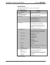
QM-MD5x1 Specifications (continued)
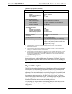
SPECIFICATION DETAILS
Audio Input Details
Format
Maximum Line-level Input
Input Impedance
Bandwidth
Stereo, unbalanced
2 V
RMS
10k Ohm
20 Hz to 20k Hz
Audio Output Performance
Max. Line-level output
Output Impedance
Bandwidth
Signal-to-Noise Ratio
Total Harmonic Distortion
2 V
RMS
unbalanced, 4 V
RMS
balanced
100 Ohms unbalanced, 200 Ohms balanced
20 Hz to 20k Hz
90 dB max
0.05%
QuickMedia Performance
Gain
Nominal input impedance
Nominal output impedance
Differential input impedance
Differential output impedance
0 dB
100 Ohms
100 Ohms
50 Ohms common
50 Ohms common
QM-MD5x1 Firmware QM-MD5x1.v4.3.031.upg or later
Rack Space 1U high
Operating Temperature and Humidity 41º to 104º F (5º to 40º C),
10 to 90% Relative Humidity (non-condensing)
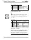
Dimensions and Weight Height: 1.70 in (4.32 cm) without mounting feet
Width: 17.03 in (43.24 cm) without mounting ears
Depth: 7.15 in (18.17cm)
Weight: 3.2 lbs (1.5 kg)
1. The latest software versions can be obtained from the Crestron website. Refer to the NOTE
following these footnotes.
2. Crestron 2-Series control systems include the AV2 and PRO2. Consult the latest Crestron Product
Catalog for a complete list of 2-Series control systems.
3. Longer lengths of CAT5/5E/6 cable can be used. However, the cumulative skew must be ≤ 15 ns for
the entire length of cable used between all QM devices. Longer lengths of cable may experience
eventual loss of bandwidth when viewing higher resolution sources. For more information, refer to
“QuickMedia Wiring” on page 16.
NOTE: Crestron software and any files on the website are for Authorized Crestron
dealers and Crestron Authorized Independent Programmers (CAIP) only. New users
may be required to register to obtain access to certain areas of the site (including the
FTP site).
Physical Description
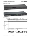
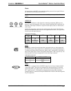
The MD5x1 is housed in a black enclosure with labeling on the front and rear panels.
Fifteen buttons with accompanying light emitting diodes (LEDs) on the front panel
are used for local control of source and destination signal switching and volume
adjustment. The source and destination selection buttons can be custom-labeled with
Crestron Engraver software and 100-pound paper. Two LEDs on the front panel
indicate power and network activity. All audio, video, QM, Cresnet
®
, and power
connections are made to the back of the unit. A pushbutton on the rear panel with an
accompanying LED is used to set the MD5x1’s network ID. Refer to the following
illustrations of the front and rear panels and the physical views.
Two mounting ears are provided for rack mounting, and four square rubber feet are
supplied for stability and to prevent slippage in tabletop placement or stacking
configurations.
Operations Guide - DOC. 6300 QuickMedia™ Matrix Switcher/Mixer: QM-MD5x1 • 7


