


Crestron QM-MD5x1 QuickMedia™ Matrix Switcher/Mixer
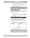
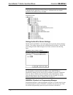
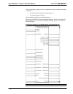
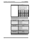
The programming symbol in slot (Slot 1) is for programming the switching functions
of the MD5x1. The second slot (Slot 2) is for programming the MD5x1’s
microphone controls. Slot 3
is for programming the mixer (EQ) settings for the
microphone signals that are received from the QM input. Slot 4 contains the
programming symbol for the audio output’s graphic EQ controls. Slot 5 is for
programming the MD5x1’s general audio controls.
The following describes each of the symbols contained in the MD5x1 object in the
SIMPL Windows Programming Manager.
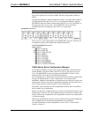
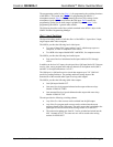
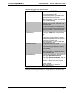
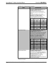
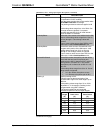
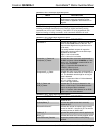
Slot 1: Input Switching
The Input Switching module is built into Slot 1 of the MD5x1. It provides a 5-input,
single-output audio/video crosspoint.
The MD5x1 provides the following local video inputs:
• Two sets of (three) BNC inputs labeled 1 and 2, which accept up to two
composite, S-video or component video sources.
• Two RGB video inputs labeled RGB 3 and RGB 4, for computer sources.
The MD5x1 provides the following local audio inputs:
• Four stereo line-level unbalanced audio inputs labeled AUD 1 through
AUD 4.
In addition to the local AV inputs, the unit provides a QM input labeled IN 5 that can
receive video, stereo program audio and two channels of microphone audio (MIC 1
and MIC 2) from QM transmitters via CAT5.
The QM input is a QM audio receiver circuit that supports up to 254 "QM Link"
presets for peaking and boost. The peaking and boost settings improve the
transmission of the encoded audio signal over long cable lengths.
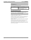
The MD5x1 provides the following audio/video outputs:
• One QM output labeled OUT.
• One stereo line-level program balanced audio output with mute relays
labeled AUDIO OUT PRG.
• One monaural line-level speech balanced audio output with mute relays
labeled AUDIO OUT SP
The unit provides the following switching scheme:
• Any of the five video sources can be switched into the QM output.
• Any of the five program audio sources can be switched into the stereo
program channel of the QM output. The audio source that is switched to the
QM output will also be routed to the mixing section of AUDIO OUT.
• The remote microphone pair from IN 5 can be switched and mixed into the
MIC 1 channel of OUT. The same mic mix will be routed to the mixing
section of AUDIO OUT.
Operations Guide - DOC. 6300 QuickMedia™ Matrix Switcher/Mixer: QM-MD5x1 • 27