


QuickMedia™ Matrix Switcher/Mixer Crestron QM-MD5x1
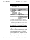
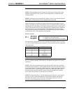
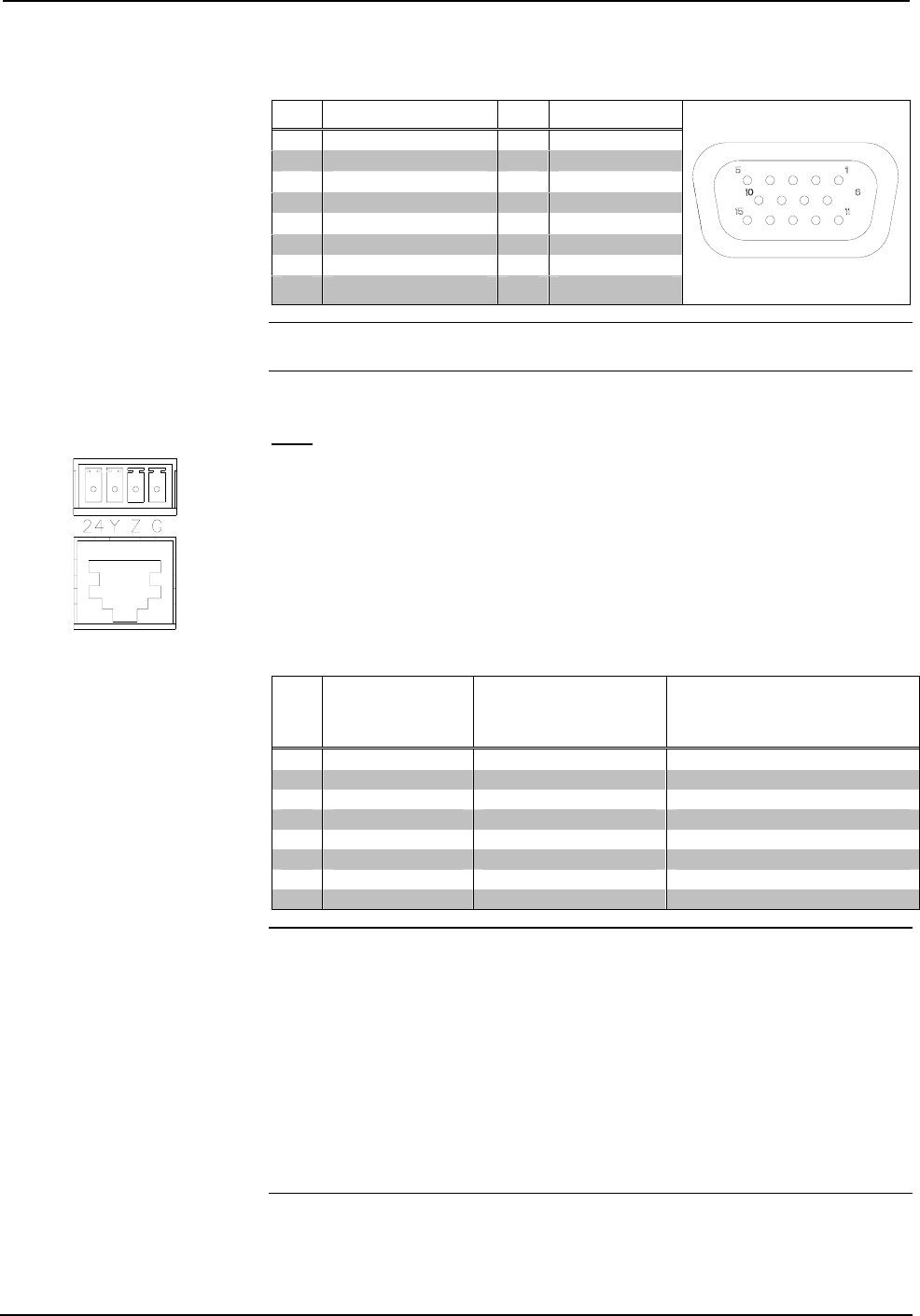
RGB DB15HD Pin Assignments
PIN FUNCTION PIN FUNCTION
1 Red Video 9 No Connect
2 Green Video 10 Ground
3 Blue Video 11 No Connect
4 Reserved 12 Monitor Sense 1
5 Ground 13 Horizontal Sync
6 Red Ground 14 Vertical Sync
7 Green Ground 15 Monitor Sense 2
8 Blue Ground
NOTE: When looking at the MD5x1, pin 1 is the top-right pin on the connector. Pin
15 is located on the bottom-left of the connector.
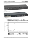
IN 5
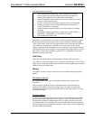
The MD5x1 contains a QM input port for connecting a QM source. This port is
designated as input 5. The QM port has an RJ-45 port for QM signals and a
corresponding 4-position mini-terminal block connector for Cresnet control signals.
For wiring information, refer to “QuickMedia Wiring” on page 16 and “Network
Wiring” on page 14.
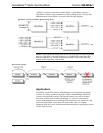
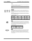
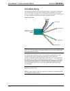
RJ-45 Pin Assignments
PIN WIRE
COLORS
(568B)
QM ASSIGNMENT:
RGB
QM ASSIGNMENT
COMPOSITE, S-VIDEO
AND AUDIO
1 WHITE/ORANGE - RGB Red - CHROMINANCE
2 ORANGE + RGB Red + CHROMINANCE
3 WHITE/GREEN - RGB Green - LUMINANCE
4 BLUE + Digital Audio + AUDIO
5 WHITE/BLUE - Digital Audio - AUDIO
6 GREEN + RGB Green + LUMINANCE
7 WHITE/BROWN - RGB Blue - COMPOSITE
8 BROWN + RGB Blue + COMPOSITE
NOTE: When transmitting S-video, luminance uses the green video pathway, and
chrominance uses the red video pathway. When transmitting composite video, the
signal is carried on the blue video pathway.
NOTE: Use Crescat-QM, or good quality CAT5E / CAT6 cable to make QM
connections. The cumulative skew over the entire length must be less than 15 ns.
Refer to “QuickMedia Wiring” on page 16 for cable specifications.
NOTE: When using Crescat-QM wiring, four additional wires are included for
making Cresnet connections. Refer to “QuickMedia Wiring” on page 16 for cable
specifications.
10 • QuickMedia™ Matrix Switcher/Mixer: QM-MD5x1 Operations Guide - DOC. 6300