


Crestron QM-MD5x1 QuickMedia™ Matrix Switcher/Mixer
Ports
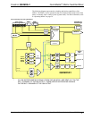
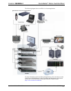
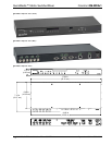
All connections to the MD5x1 are made through the ports on the rear panel. Refer to
the illustrations and descriptions that follow.
NOTE: Interface connectors for the audio and NET ports are provided with the
MD5x1.
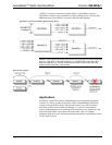
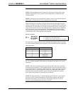
VIDEO IN
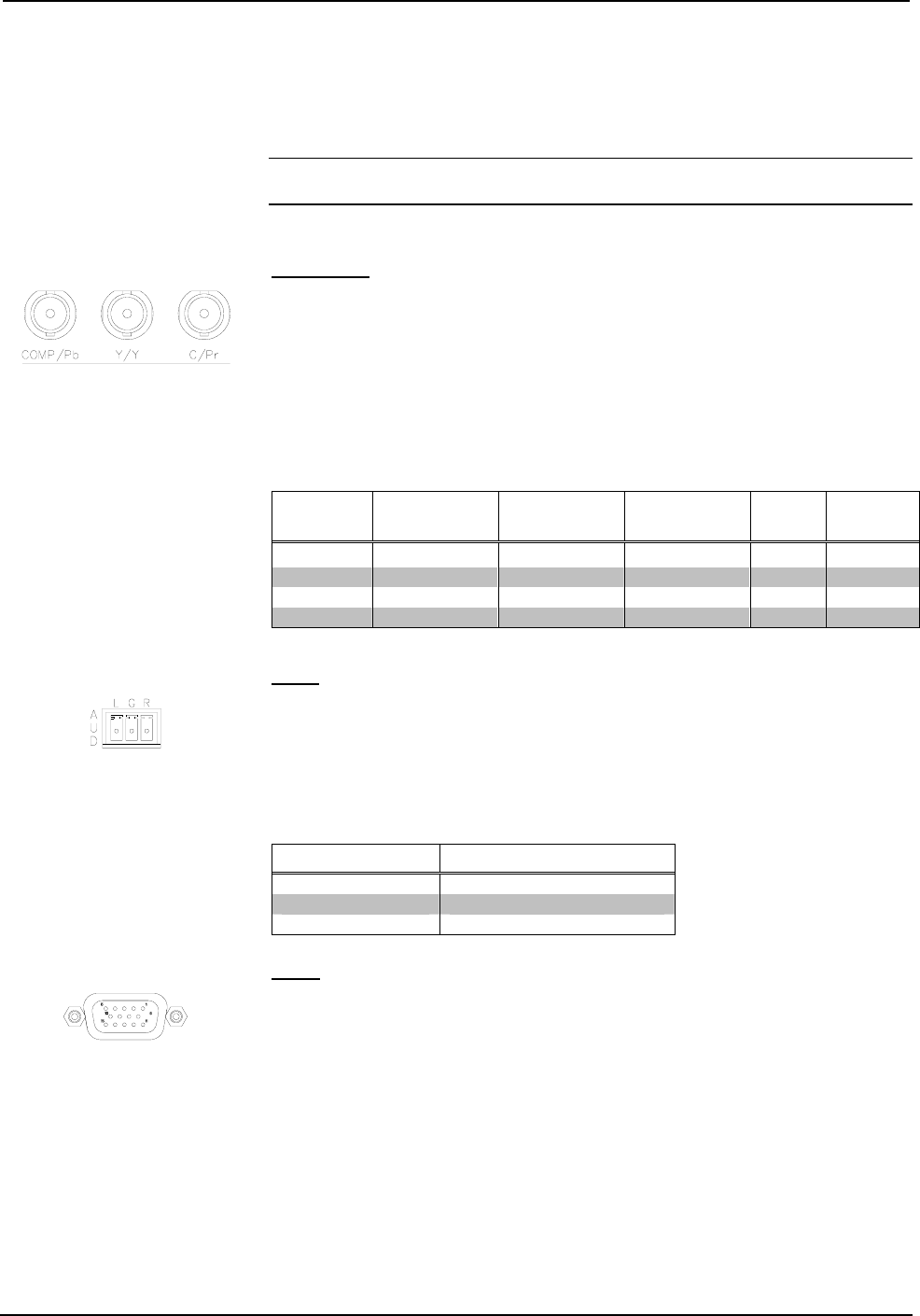
The MD5x1 contains two video inputs for connecting component, RGB (sync-on-
green), S-video, and composite video source signals using three BNC connectors for
each input. Each input is linked to a respective audio input (Video In 1 linked to the
AUD 1 port).
Connect the appropriate connectors for each incoming video signal. The following
table lists the connections to be used for each signal format as well as the signal lines
used for sync and signal detection.
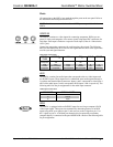
Video Input Connections
SIGNAL
TYPE
COMP/P
B
Y/Y C/P
R
SYNC SENSE
Component
P
B
Y
P
R
Y Y
RGB Blue Green Red G G
S-video Not connected Luma Chroma N/A Luma
Composite Composite Not Connected Not Connected N/A Composite
AUD
The MD5x1 contains four audio inputs that correspond to the two video inputs and
two RGBHV inputs. These inputs receive unbalanced stereo audio signals through a
3-position mini-terminal block connector. Inputs 1 and 2 correspond to video inputs 1
and 2 while audio inputs 3 and 4 correspond to RGB inputs 3 and 4 respectively. The
following table lists the pin assignments for the audio input connector.
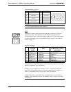
Audio Input Connections
PIN NAME SIGNAL NAME
L Left
G Ground
R Right
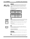
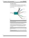
RGB
The MD5x1 is equipped with two RGBHV inputs for receiving a computer’s RGB
video output signal. These ports can automatically detect the presence of an RGB
signal using the H-sync signal on pin 13 and can sync on the H signal on pin 13 or
the V signal on pin 14. A buffered pass-through port for connecting a secondary
computer display is connected to the port labeled RGB 4. Refer to the following table
for pin-assignments.
Operations Guide - DOC. 6300 QuickMedia™ Matrix Switcher/Mixer: QM-MD5x1 • 9