


QuickMedia™ Matrix Switcher/Mixer Crestron QM-MD5x1
66 • QuickMedia™ Matrix Switcher/Mixer: QM-MD5x1 Operations Guide - DOC. 6300
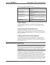
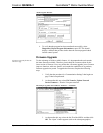
When the verbose mode is on and the routing status changes while the MD5x1 is in
the system mode, or if the MD5x1 is polled for the status of an output, the MD5x1
replies with one of the responses listed in the following table.
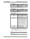
Switching/Routing Status Replies
MESSAGE DEFINITION
IxO1A\r
New audio route if audio route has changed
where x will be a two-digit number from 00 to
05.
IxO1V\r
New video route if video route has changed
where x will be a two-digit number from 00 to
05.
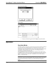
SA1V1M1\r Current switching schema of all of the outputs
where a1 is the input routed to the QM output
audio channel, v1 is the input routed to the QM
output video channel, and m1 is the
microphone input routed to the QM output
microphone channel. Each number will be two
digits.
If a switch command is sent and an output is already at the new setting, serial
feedback will not be provided for that output.
NOTE: There is no serial feedback for any switches made while the MD5x1 is in
the local mode, even if the verbose mode is on. Use the LocalMode-FB digital
signal to signal when the device leaves local mode in order to trigger the “S?\r”
command to query the MD5x1 for the current status of all outputs.
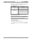
“Switch All” Example
The string “C020401\r” sends the following command:
• Switch Audio Input 2, Video Input 4 and no microphone signal to QM Out.
If polled for the status of all outputs (S?\r), the device response on Control-FB$ will
be: “S020400\r”.