


Crestron QM-MD5x1 QuickMedia™ Matrix Switcher/Mixer
AUDIO OUT
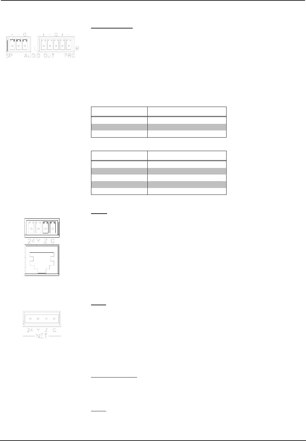
The line-level audio output follows the output of the QM output port. The output
consists of a 3-position mini-terminal block connector for speech output and a
5-position mini-terminal block connector for stereo program audio output. This
output provides balanced or unbalanced line-level output for use by an audio
amplifier.
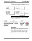
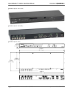
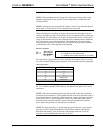
The following tables list the pin assignments (from left to right) for the 3-position
and 5-position mini-terminal block connectors. For additional information, refer to
“Hardware Hookup” on page 22.
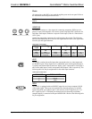
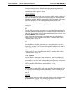
Speech Output Connections
PIN NAME SIGNAL NAME
+ Positive
- Negative
G Ground
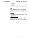
Program Audio Output Connections (left to right)
PIN NAME SIGNAL NAME
+ Positive (left)
- Negative (left)
G Ground (right and left)
+ Positive (right)
- Negative (right)
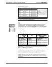
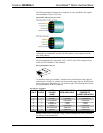
OUT
The MD5x1 has a QM port for connecting a QM receiver or any other device with a
QM input. The QM port has an RJ-45 connector for QM signals and a corresponding
4-position mini-terminal block connector for Cresnet control signals.
The QM pin assignments for the OUT port are the same as the IN 5 port described
previously.
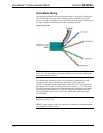
For wiring information, refer to “QuickMedia Wiring” on page 16 and “Network
Wiring” on page 14.
For additional information, refer to “Hardware Hookup” on page 22.
NET
This 4-position terminal block connector is used to connect the MD5x1 to the
Cresnet system. Data and power for the MD5x1 are provided via the connection.
Refer to “Network Wiring” on page 14.
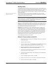
Indicators & Pushbuttons
The MD5x1s indicators and pushbuttons are described in the following paragraphs.
PWR (Power)
This LED, located on the front panel, illuminates when 24 VDC is supplied to the
MD5x1 via the NET port.
NET
This LED, located on the front panel, illuminates when communication between the
control system and the MD5x1 is established (the unit is polled on the network).
Operations Guide - DOC. 6300 QuickMedia™ Matrix Switcher/Mixer: QM-MD5x1 • 11