


Crestron QM-MD5x1 QuickMedia™ Matrix Switcher/Mixer
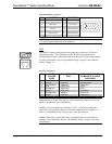
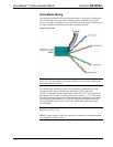
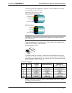
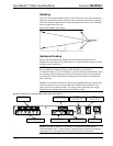
The following diagram illustrates how composite, S-video, and RGB video signals
are transmitted over the CAT5E wire.
Quick Media Video Signals on CAT5E
NOTE: When transmitting S-video or composite video, luminance uses the green
video pathway, chrominance uses the red video pathway, and composite uses the
blue video pathway.
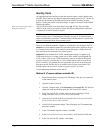
The pin assignments for Crescat-QM, CAT5, CAT5E, and CAT6 wiring are based
on the EIA/TIA 568B RJ-45 Jack standard.
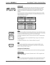
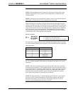
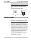
RJ-45 QuickMedia Connector
Pin 1
To determine which pin is number 1, hold the cable so that the end of the eight-pin
modular jack is facing you, with the clip down and the copper side up. When looking
down at the copper connections, pin 1 is on the far right. The following table lists the
pin assignments on the RJ-45 connector.
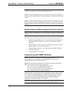
Pin and Pair Assignment
RJ-45
PIN #
CAT5E
PAIR #
WIRE
COLORS
(568B)
QM ASSIGNMENT
RGB AND AUDIO
QM ASSIGNMENT
COMPOSITE,
S-VIDEO AND AUDIO
1 2 WHITE/ORANGE - RGB RED - CHROMINANCE
2 2 ORANGE + RGB RED + CHROMINANCE
3 3 WHITE/GREEN - RGB GREEN - LUMINANCE
4 1 BLUE + AUDIO + AUDIO
5 1 WHITE/BLUE - AUDIO - AUDIO
6 3 GREEN + RGB GREEN + LUMINANCE
7 4 WHITE/BROWN - RGB BLUE - COMPOSITE
8 4 BROWN + RGB BLUE + COMPOSITE
NOTE: When using Crescat-QM wiring, a cable containing four wires is included
for making Cresnet connections.
Operations Guide - DOC. 6300 QuickMedia™ Matrix Switcher/Mixer: QM-MD5x1 • 17