


QuickMedia™ Matrix Switcher/Mixer Crestron QM-MD5x1
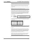
Stacking
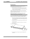
Four "feet" are provided with the MD5x1 so that if the unit is not rack mounted, the
rubber feet can provide stability when the unit is placed on a flat surface or stacked.
These feet should be attached prior to the hookup procedure. Refer to the illustration
below for placement of the feet.
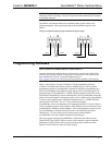
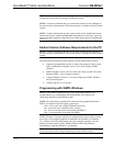
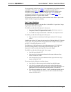
Feet Location (Bottom View of Unit)
ATTACH FEET
NEAR CORNERS
OF THE UNIT
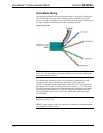
Hardware Hookup
Refer to the following hookup diagram and, aside from attaching power last,
complete the connections in any order. Refer to “Network Wiring” on page 14 when
making network connections.
NOTE: To prevent overheating, do not operate this product in an area that exceeds
the environmental temperature range listed in the table of specifications.
Consideration must be given if installed in a closed or multi-unit rack assembly since
the operating ambient temperature of the rack environment may be greater than the
room ambient. Contact with thermal insulating materials should be avoided on all
sides of the unit.
NOTE: The maximum continuous current from equipment under any external load
conditions shall not exceed a current limit that is suitable for the minimum wire
gauge used in interconnecting cables. The ratings on the connecting unit's supply
input should be considered to prevent overloading the wiring.
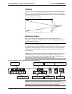
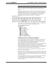
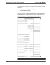
Hardware Connections for the QM-MD5x1 (Back of the Unit is Shown)
CRESNET:
TO CONTROL SYSTEM AND
OTHER CRESNET DEVICES
QM OUTPUT:
QUICKMEDIA PORT CARRIES
AUDIO, VIDEO, RGB, MICROPHONE,
AND CRESNET SIGNALS
QM INPUT:
QUICKMEDIA PORT CARRIES
AUDIO, VIDEO, RGB, MICROPHONE,
AND CRESNET SIGNALS
LINE LEVEL OUTPUTS:
CARRY SPEECH AND AUDIO
PROGRAM TO AUDIO AMPLIFIER
VIDEO INPUTS:
FROM YP
B
P
R
, S-VIDEO,
COMPOSITE, OR RGB SOURCES
RGB INPUTS:
FROM PC RGB SOURCES
BUFFERED OUTPUT FOR RGB4:
COMPUTER LOOP-THROUGH TO
COMPUTER MONITOR (IF USED)
STEREO AUDIO INPUTS:
(PAIR WITH THE 2 VIDEO
INPUTS AND 2 RGB INPUTS)
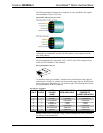
NOTE: The MD5x1 can only be powered by the 4-position terminal block
connector labeled “NET”. Power cannot be supplied from network devices that are
connected to the mini-terminal block connectors located on the QM ports.
22 • QuickMedia™ Matrix Switcher/Mixer: QM-MD5x1 Operations Guide - DOC. 6300