CY7C67300
Document #: 38-08015 Rev. *J Page 49 of 99
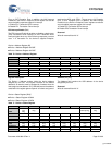
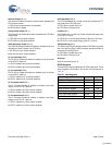
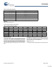
Receive Disable (Bit 12)
The Receive Disable bit enables or powers down (disables) the
OTG receiver section.
1: OTG receiver powered down and disabled
0: OTG receiver enabled
Charge Pump Enable (Bit 11)
The Charge Pump Enable bit enables or disables the OTG VBus
charge pump.
1: OTG VBus charge pump enabled
0: OTG VBus charge pump disabled
VBUS Discharge Enable (Bit 10)
The VBUS Discharge Enable bit enables or disables a 2K ohm
discharge pull down resistor onto OTG VBus.
1: 2K ohm pull down resistor enabled
0: 2K ohm pull down resistor disabled
D+ Pull-up Enable (Bit 9)
The D+ Pull-up Enable bit enables or disables a pull up resistor
on the OTG D+ data line.
1: OTG D+ dataline pull up resistor enabled
0: OTG D+ dataline pull up resistor disabled
D– Pull-up Enable (Bit 8)
The D– Pull-up Enable bit enables or disables a pull up resistor
on the OTG D– data line.
1: OTG D– dataline pull up resistor enabled
0: OTG D– dataline pull up resistor disabled
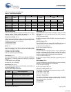
D+ Pull-down Enable (Bit 7)
The D+ Pull-down Enable bit enables or disables a pull down
resistor on the OTG D+ data line.
1: OTG D+ dataline pull down resistor enabled
0: OTG D+ dataline pull down resistor disabled
D– Pull-down Enable (Bit 6)
The D– Pull-down Enable bit enables or disables a pull down
resistor on the OTG D– data line.
1: OTG D– dataline pull down resistor enabled
0: OTG D– dataline pull down resistor disabled
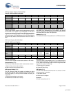
OTG Data Status (Bit 2)
The OTG Data Status bit is a read only bit and indicates the TTL
logic state of the OTG VBus pin.
1: OTG VBus is greater then 2.4V
0: OTG VBus is less then 0.8V
ID Status (Bit 1)
The ID Status bit is a read only bit that indicates the state of the
OTG ID pin on Port A.
1: OTG ID Pin is not connected directly to ground (>10K ohm)
0: OTG ID Pin is connected directly ground (< 10 ohm)
VBUS Valid Flag (Bit 0)
The VBUS Valid Flag bit indicates whether OTG VBus is greater
then 4.4V. After turning on VBUS, firmware must wait at least 10
µs before this reading this bit.
1: OTG VBus is greater then 4.4V
0: OTG VBus is less then 4.4V
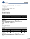
Reserved
Write all reserved bits with ’0’.
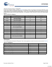
GPIO Registers
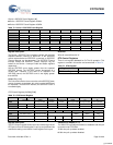
There are seven registers dedicated for GPIO operations. These
seven registers are covered in this section and summarized in
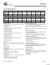
Table 76.
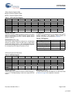
Table 76. GPIO Registers
Register Name Address R/W
GPIO Control Register 0xC006 R/W
GPIO0 Output Data Register 0xC01E R/W
GPIO0 Input Data Register 0xC020 R
GPIO0 Direction Register 0xC022 R/W
GPIO1 Output Data Register 0xC024 R/W
GPIO1 Input Data Register 0xC026 R
GPIO1 Direction Register 0xC028 R/W
[+] Feedback


