CY7C67300
Document #: 38-08015 Rev. *J Page 77 of 99
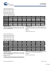
PWM n Start Register [R/W]
■ PWM 0 Start Register 0xC0EA
■ PWM 1 Start Register 0xC0EE
■ PWM 2 Start Register 0xC0F2
■ PWM 3 Start Register 0xC0F6
Register Description
The PWM n Start register designates where in the window
defined by the PWM Maximum Count register to start the PWM
pulse for a supplied channel.
Address (Bits [9:0])
The Address field designates when to start the PWM pulse. If this
start value is equal to the Stop Count Value then the output stays
at false.
Reserved
Write all reserved bits with ’0’.
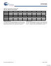
PWM n Stop Register [R/W]
■ PWM 0 Stop Register 0xC0EC
■ PWM 1 Stop Register 0xC0F0
■ PWM 2 Stop Register 0xC0F4
■ PWM 3 Stop Register 0xC0F8
Register Description
The PWM n Stop register designates where in the window
defined by the PWM Maximum Count register to stop the PWM
pulse for a supplied channel.
Address (Bits [9:0])
The Address field designates when to stop the PWM pulse. If the
PWM Start value is equal to the PWM Stop value then the output
stays at ‘0’. If the PWM Stop value is greater then the PWM
Maximum Count value then the output stays at true.
Reserved
Write all reserved bits with ’0’.
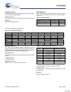
Table 128. PWM n Start Register
Bit # 15 14 13 12 11 10 9 8
Field Reserved Address...
Read/Write - - - - - - R/W R/W
Default 0 0 0 0 0 0 0 0
Bit # 7 6 5 4 3 2 1 0
Field ...Address
Read/Write R/W R/W R/W R/W R/W R/W R/W R/W
Default 0 0 0 0 0 0 0 0
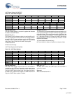
Table 129. PWM n Stop Register
Bit # 15 14 13 12 11 10 9 8
Field Reserved Address...
Read/Write - - - - - - R/W R/W
Default 0 0 0 0 0 0 0 0
Bit #
7 6 5 4 3 2 1 0
Field ...Address
Read/Write R/W R/W R/W R/W R/W R/W R/W R/W
Default 0 0 0 0 0 0 0 0
[+] Feedback


