


Introduction 23
Understanding the Stack Topology
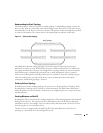
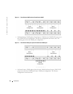
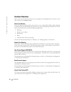
The PowerConnect 3400 series operates in a Ring topology. A stacked Ring topology is where all
devices in the stack are connected to each other forming a circle. Each device in the stack accepts
data and sends it to the device to which it is attached. The packet continues through the stack until
it reaches its destination. The system discovers the optimal path on which to send traffic.
Figure 1-3. Stacking Ring Topology
Most difficulties incurred in Ring topologies occur when a device in the ring becomes non-
functional, or a link is severed. With the PowerConnect 3424/P and PowerConnect 3448/P stack,
the system automatically switches to a Stacking Failover topology without any system downtime.
An SNMP message is automatically generated, but no stack management action is required.
However, the stacking link or stacking member must be repaired to ensure the stacking integrity.
After the stacking issues are resolved, the device can be reconnected to the stack without
interruption, and the Ring topology is restored.
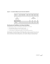
Stacking Failover Topology
If a failure occurs in the stacking topology, the stack reverts to Stacking Failover Topology. In the
Stacking Failover topology, devices operate in a chain formation. The Stack Master determines
where the packets are sent. Each unit is connected to two neighboring devices, except for the top
and bottom units.
Stacking Members and Unit ID
Stacking Unit IDs are essential to the stacking configuration. The stacking operation is determined
during the boot process. The operation mode is determined by the Unit ID selected during the
initialization process. For example, if the user selected the stand-alone mode, the device boots in
the boot-up process as a stand-alone device.
The device units are shipped with a default Unit ID of the stand-alone unit. If the device is
operating as a stand-alone unit, all stacking LEDs are off.
Ring Topology