


Installing the PowerConnect 3424/P and PowerConnect 3448/P 57
6
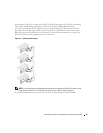
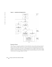
Selection Process
— To advance the stacking ID LED number, continue pressing the Stack ID
button. When LED 6 is flashing, pressing the Stack ID button results in the device being configured
as a stand-alone. Pressing the Stack ID button again advances the Stack ID to 1. Unit 1 and Unit 2
are master-enabled units. See "Stacking Overview" master-election process.
7
End selection process
— The unit ID selection process is completed when the 15-second
flashing period has transpired. The Stack ID button becomes unresponsive and the unit ID is
set to the LED ID flashing at the end of the period.
NOTE: These steps should be performed one unit at a time until all stack members are powered up and
their Stack IDs are selected. Performing the steps one unit at a time will allow for sufficient time to select
the Stack ID for each unit. However, the entire stack should be cabled as per the "Stacking Cable
Diagram" before powering up the devices.
Starting and Configuring the Device
After completing all external connections, connect a terminal to the device to configure the device.
Performing the additional advanced functions is described in the section "Advanced
Configuration".
NOTE: Before proceeding, read the release notes for this product. Download the release notes from the
Dell Support website at support.dell.com.
NOTE: It is recommended that you obtain the most recent revision of the user documentation from the
Dell Support website at support.dell.com.
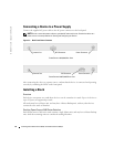
Connecting to the Device
To configure the device, the device must be connected to a console. However, if the device is part
of a stack, only one device called the Master unit in the stack needs to be connected to a terminal.
Because the stack operates as a single device, only the Master unit is configured.
Connecting the Terminal to the Device
The device provides a Console port that enables a connection to a terminal desktop system running
terminal emulation software for monitoring and configuring the device. The Console port
connector is a male DB-9 connector, implemented as a data terminal equipment (DTE) connector.
To use the Console port, the following is required:
• VT100-compatible terminal or a desktop or portable system with a serial port and running
VT100 terminal emulation software
• An RS-232 crossover cable with a female DB-9 connector for the Console port and the
appropriate connector for the terminal
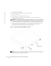
To connect a terminal to the device Console port:
1
Connect the supplied RS-232 crossover cable to the terminal running VT100 terminal
emulation software.
2
Select the appropriate serial port (serial port 1 or serial port 2) to connect to the console.