


38 Hardware Description
www.dell.com | support.dell.com
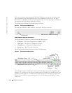
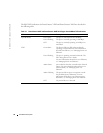
There are two buttons on the front panel. The Stack ID button is used to select the unit number.
The second button is the Reset Button which is used to manually reset the device. The Reset
button does not extend beyond the unit’s front panel surface, so reset by pressing it accidentally is
prevented. On the front panel are all the device LEDs.
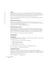
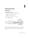
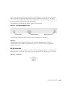
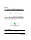
The following figure illustrates the PowerConnect 3424 back:
Figure 2-2. PowerConnect 3424 Back Panel
The back panel contains an RPS connector, console port, and power connector.
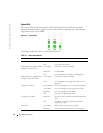
PowerConnect 3448 Port Description
The PowerConnect 3448 device is configured with the following ports:
•
48 FE ports
— RJ-45 ports designated as 10/100Base-T ports
•
2 Fiber ports
— Designated as 1000Base-X SFP ports
•
2 Gigabit ports
— Designated as 1000Base-T ports
•
Console port
— RS-232 Console based port
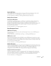
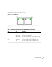
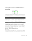
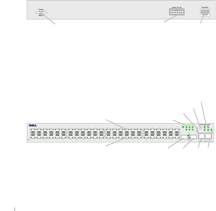
The following figure illustrates the PowerConnect 3448 front panel.
Figure 2-3. PowerConnect 3448 Front Panel
The front panel contains 48 RJ-45 ports number 1-48. The upper row of ports is marked by odd
numbers 1-47, and the lower row of ports is marked with even numbers 2-48. In addition, the front
panel also contains ports G1 - G2 which are fiber ports and ports G3- G4 which are copper ports.
Ports G3- G4 can either be used as stacking ports, or used to forward network traffic in a stand-
alone device.
Console Port
RPS Connector
Power Connector
10/100 Base-T Ports 1, 3, 5, 7, ...47
10/100 Base-T Ports 2, 4, 6, 8, ...48
Stacking LEDs
Stacking Button
Reset Button
System LEDs
G1
G2
G3
G4
1000Base-X
SFP Ports
Stacking
Ports