


Configuring Switch Information 291
Configuring Multiple Spanning Tree
MSTP operation maps VLANs into STP instances. Multiple Spanning Tree provides differing load
balancing scenario. For example, while port A is blocked in one STP instance, the same port is
placed in the
Forwarding State
in another STP instance.
In addition, packets assigned to various VLANs are transmitted along different paths within
Multiple Spanning Trees Regions (MST Regions). Regions are one or more Multiple Spanning Tree
bridges by which frames can be transmitted. To open the
MSTP Settings
page, click
Switch
→
Spanning Tree
→
MSTP Settings
in the tree view
.
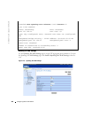
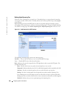
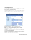
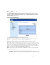
Figure 7-26. MSTP Settings
The
MSTP Settings
page contains the following fields:
Region Name (1-32 Characters)
— Indicates user-defined MSTP region name.
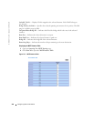
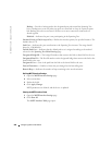
Revision
(0-65535) — Defines unsigned 16-bit number that identifies the current MST
configuration revision. The revision number is required as part of the MST configuration.
The possible field range is 0-65535.
Max Hops (1-40)
— Defines the total number of hops that occur in a specific region before the
BPDU is discarded. Once the BPDU is discarded, the port information is aged out. The possible
field range is 1-40. The field default is 20 hops.
IST Master
— Indicates the Internal Spanning Tree Master ID. The IST Master is the instance 0 root.
Instance ID
— Defines the MSTP instance. the field range is 1-15.