


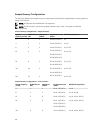
System Capacity
(in GB)
DIMM Size (in
GB)
Number of
DIMMs
Organization and
Speed
DIMM Slot Population
2R x4, 1600 MT/s
96 16 6
2R x4, 1333 MT/s
2R x4, 1600 MT/s
A1, A2, A3, B1, B2, B3
192 32 6
4R x4, 1333 MT/s
A1, A2, A3, B1, B2, B3
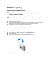
Removing Memory Modules
WARNING: The DIMMs are hot to touch for some time after the blade has been powered down.
Allow time for the DIMMs to cool before handling them. Handle the DIMMs by the card edges and
avoid touching the DIMM components.
CAUTION: Many repairs may only be done by a certified service technician. You should only
perform troubleshooting and simple repairs as authorized in your product documentation, or as
directed by the online or telephone service and support team. Damage due to servicing that is
not authorized by Dell is not covered by your warranty. Read and follow the safety instructions
that came with the product.
CAUTION: To ensure proper system cooling, memory-module blanks must be installed in any
memory socket that is not occupied. Remove memory-module blanks only if you intend to install
memory modules in those sockets.
CAUTION: If you are permanently removing a processor, you must install a socket protective cap
and a processor/DIMM blank in the vacant socket to ensure proper system cooling. The
processor/DIMM blank covers the vacant sockets for the DIMMs and the processor.
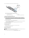
1. Remove the blade from the sleeve.
2. Remove the blade system board.
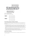
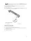
3. Locate the memory module socket(s).
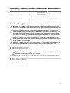
CAUTION: Handle each memory module only by the card edges, making sure not to touch
the middle of the memory module or gold contacts.
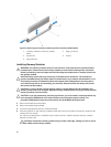
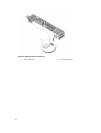
4. Press down and out on the ejectors on each end of the socket until the memory module pops out of
the socket.
5. Install memory-module blanks in vacant memory-module socket(s) to ensure proper system cooling.
6. Install the blade system board.
7. Install the blade in the sleeve.
49