


Fast Ethernet Switching System User’s Guide
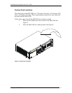
Connecting the DES-5200 to the Network
20
3
Connecting the DES-5200 to the
Network
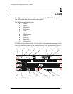
This chapter covers the following:
• Cable Specifications
• Ports
• Connecting the DES-5200 to another DES-5200
• Connecting the DES-5200 to other switches and hubs
This section deals with making cables and connecting the DES-5200 to other
devices. It is extremely important that cables have the correct pin arrangement
and that the proper cables be used when connecting to servers, switches, hubs,
workstations and other devices.
Cable Specifications
Use the following guidelines when handling cables:
• Do not stretch or bend cables.
• Do not put copper cables near sources of electromagnetic
interference. Fiber optic cables are immune to most
electromagnetic interference.
• Do not create trip hazards by laying cables in aisles and walkways.
• Secure cables to the floor when routing in aisles or walkways.
Do not use telephone cable. Telephone cable does not support Ethernet or Fast
Ethernet.
Copper Cable
In order for Ethernet or Fast Ethernet to work the wires must be arranged
correctly inside the RJ-45 connector. The most common problem on Ethernet or
Fast Ethernet networks is the cable. If you migrate from Ethernet to Fast Ethernet,
make sure the cables are pinned out properly.
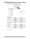
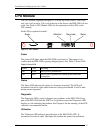
There are two types of cables: straight through and crossover. Category 3, 4, and
5 UTP/STP cable has eight wires inside the sheath. The wires form four pairs.
Straight through cable has the same pin out, inside the RJ-45 connector, at both
ends. Crossover cable has a different pin arrangement at each end. Fast Ethernet
does not tolerate incorrect pin arrangements. You must use the correct pin
arrangement in order for the DES-5200 to work properly. See Figure 11, for an
example of straight through and crossover cable.