


Fast Ethernet Switching System User’s Guide
LEDs
27
CPU Module
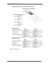
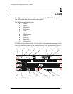
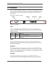
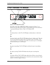
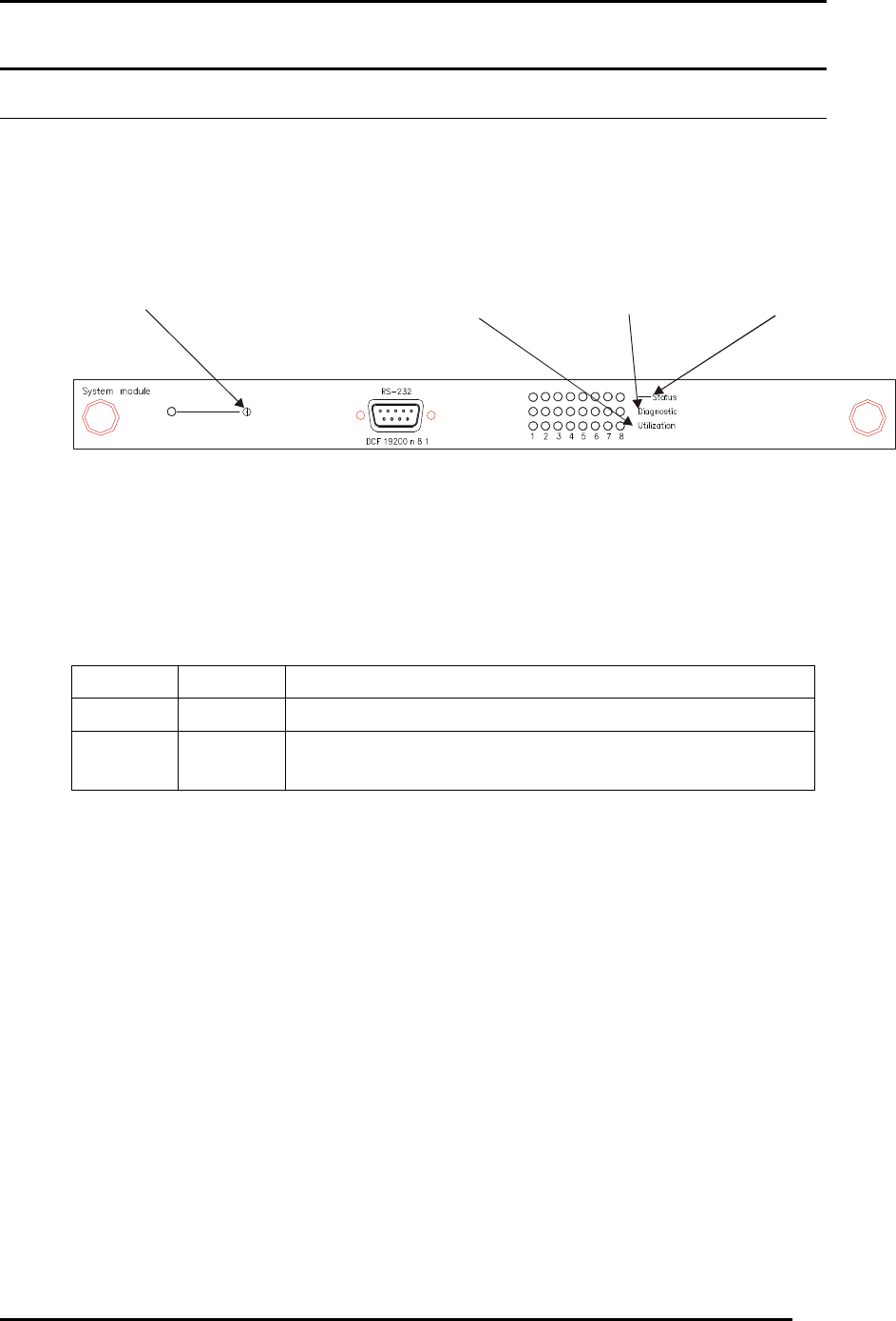
The CPU module, displayed in Figure 13, is at the top of the chassis. This is the
only slot it will work in. If it is not at the top of the chassis, the DES-5200 will not
work. See Table 6: CPU Module LEDs for an explanation of the LEDs on the
CPU module.
Each LED is explained in detail.
Figure 13: CPU Module
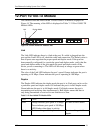
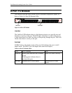
Power
The power LED lights when the DES-5200 is powered on. The purpose is to
confirm that the DES-5200 is getting adequate power. See Table 5: Power LED.
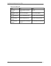
Table 5: Power LED
Status Color Meaning
On Green DES-5200 is powered on
Off Dark DES-5200 is powered off, check power cable and
connection
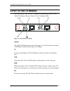
Status
The Status LED indicates the status of a firmware download. The LED will
increment from left to right while firmware is being downloaded. It will be dark
during normal operation.
Diagnostic
The Diagnostic LED is used to diagnose any problems on the DES-5200. If any
part of the DES-5200 fails the POST or if a problem occurs the Diagnostic LED
displays a code indicating the problem. See Chapter 6 for the meaning of the LED
code and a recommended action.
Utilization
The Utilization LED indicates the utilization of the DES-5200’s CPU. It
increments from left to right. The higher the number the greater the utilization.
Utilization
Diagnostic
Status
Power