


Fast Ethernet Switching System User’s Guide
LEDs
26
4
LEDs
The LED panel is designed to enable you to manage the DES-5200 at a glance.
The LEDs on each module are dealt with in detail.
The LEDs indicate the following:
• Power
• Status
• Diagnostic
• Utilization
• Link
• Speed
• Duplex mode
• Activity
• Collision
• Receiving
• Transmitting
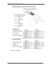
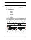
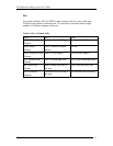
All LEDs are described in detail. Use the tables to determine the meaning of each
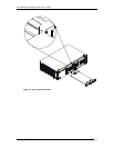
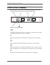
LED. All LEDs are located on the front of the DES-5200, displayed in Figure 12.
Figure 12: DES-5200 LEDs
Link
Power LED
Duplex
Utilization
Diagnostic
Status
Link/Act
Full/Half
Duplex
Collision
Receiving
Transmitting
Link
Act
Link