This is at system chassis ground potential (non-isolated).
All of the digital output status signals on this connector,
are isolated (signals are not referenced to generator chassis
ground). When a status output signal is activated, it will
sink current (500mA Max. sourced by a 24VDC supply)
to isolated common. In automation terms, the outputs are
NPN (sinking) and would drive a PNP (sourcing) input
that is referenced to the Isolated Common pin.
The digital status output signals can only sink current to
isolated common. They cannot be changed to a sourcing
(PNP) type output. If sourcing status outputs are required,
there is an optional isolated NPN to PNP conversion
module that is DIN rail mountable. The module converts
the standard isolated sinking (NPN) status output signals
to isolated sourcing (PNP) status output signals. Consult
your local sales representative for information about the
conversion module.
System Outputs Connector Pinout
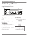
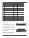
The SYSTEM OUTPUTS connector is a DB-25F (standard
D-subminiature 25 circuit female) connector. Connector
pin numbers for this connector are shown in Figure 3-11.
The male connector on the cable is a mirror image of the
panel mounted connector and is shown in Figure 3-12.
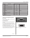
Table 3-III lists the signal names. Detailed descriptions
are listed in System Outputs Signal Descriptions that fol-
low. To assist with custom automation system wiring and
assembly, the wire color coding for the system outputs
cable is listed in Table 3-III.
System Outputs Signal
Descriptions
Pin 1 (+22V Power Supply)
This pin can supply +22VDC at up to 250mA to power
the user’s automation controls.
Pin 2 (Not Used)
Pin 2 is an open connection.
Pin 3 (+22V Power Ground)
Pin 3 is the 22VDC return and is tied to the system
chassis ground.
Pin 4 (Programmable Status Output 1)
Pin 4 is a digital active low status output that can be
reprogrammed and assigned to other system status sig-
nals (from the available selections) from the System
tab in iQ Explorer.
Pin 5 (Programmable Status Output 2)
Pin 5 is a digital active low status output that can
be reprogrammed and assigned to another system
status signal (from the available selections) from the
System tab in iQ Explorer.
Pin 6 (Ultrasound Active Status Output)
Pin 6 is a digital active low status output that activates
when the system is delivering ultrasonic power to the
load attached to the ultrasound output connector. This
output will be an open circuit when the ultrasound
output is off.
Pin 7 (Any Fault Status Output)
Pin 7 is a digital active low status output that activates
whenever any fault condition is detected that inhibits
ultrasound output and normal system operation. This
output will be an open circuit when no system fault
conditions are detected.
Generator faults that will activate the Any Fault output:
• Overload (Average, Peak, or Frequency)
• Overtemperature Fault
• System Power Fault
Pin 8 (Press Trigger Status Output)
Pin 8 is a digital active low status output that activates
when the specied trigger type has occurred. It will
remain active until the thruster head raises to the top
of the stroke. This output will be an open circuit when
a trigger condition hasn’t been detected.
Continued
Continued from previous page
Page 24
iQ Series Ultrasonic Generator/Power Supply ES User’s Manual
Dukane Manual Part No. 403-575-00


