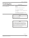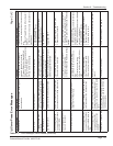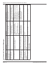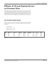
The welding cycle can be divided into a series of segments: Cycle Start,
Downstroke, Trigger, Weld Pressure 1, Weld Pressure 2, and Hold. In each
of these segments, operator action, rear panel inputs, and process limits can
affect the ow of the process. What follows are examples of how some events
can alter the ow of the welding process, and how they can be identied.
An Uninterrupted Cycle
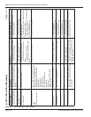
Figure 6-1 shows the results of a weld process that was not interrupted by
any I/O signal or system error. The setup conditions for this process were
as follows:
• Normal Trigger
• Weld by Time for 50 ms.
• Hold by Time for 1.0 sec.
PART DOWNSTROKE DOWNSTROKE WELD TIME WELD DIST WELD ENERGY HOLD TOTAL TOTAL
COUNT TIME DIST PRESSURE 1 PRESSURE 1 PRESSURE 1 TIME CYCLE TIME STROKE
35 0.975 1.7921 0.050 0.0023 28.4 1.000 2.025 1.8090
36 0.879 1.7927 0.050 0.0020 28.4 1.000 1.929 1.8092
37 0.877 1.7928 0.050 0.0022 28.4 1.000 1.927 1.8092
Figure 6-1 Data from an Uninterrupted Cycle
Effects of I/O and System Errors
on Process Flow
Page 87
Dukane Manual Part No. 403-575-00
Section 6 - Troubleshooting


