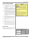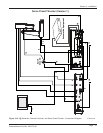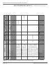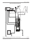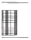
Connecting Cables
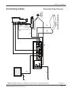
Step 1. Ground the generator chassis with the supplied
14-Gauge wire, and attach it to the grounding stud.
See Figure 3-7.
Step 2. Ultrasound (J1) - This output connects the Ul-
trasound Output of the iQ Series generator to the
transducer, through a coaxial cable. The electrical
welding signal is transmitted through this cable.
Step 3. Operational Control (J201) - This cable runs from
J201 on the thruster to the generator's Thruster
connector (J5). The generator provides controls
for triggering the weld, operating the thruster’s
pneumatic system, and providing 24 VDC oper-
ating voltage through this cable. The press driver
card in the generator also provides monitoring for
these functions.
Step 4. Encoder (J11) (Optional) - The purpose of the
encoder cable is to connect the distance encoder
option to the generator's Encoder Port (J11).
Step 5. Ethernet Cable (J9) - Connects to the PC, LAN
port.
Step 6. RS-232 Cable (J10) - Connects to the PC, RS-232
port.
Step 7. Base/Abort Cable (J6) - Connects to the press
base plate connector (J35) or an automation PLC.
Step 8. Connect the AC power cord to the IEC power
inlet connector on the ultrasonic generator, and
plug the other end into an approved AC outlet.
Power Cords
The AC line cords supplied with the standard generators
are matched to the ultrasonic output power rating and the
continent of specied use. See Table 3-IV.
CAUTION
The power cord is equipped
with a three-prong, ground-
ed-type plug for your safety.
Whenever a two-slot recep-
tacle is encountered, we
strongly recommend that it is replaced
with a properly grounded three-lead
receptacle.
Have a qualified electrician do the
replacement in accordance with the
National Electrical Code and local
codes and ordinances. DO NOT cut
off the power cord grounding prong or
alter the plug in any way.
Continent of Use Power Cord
Part Number
Power
North America
200 - 1110 240V, 15A
200 - 1541 240V, 10A
Continental Europe
200 - 1111 240V, 16A
200 - 1542 240 V, 10A
Table 3-IV Power Cords
Page 29
Dukane Manual Part No. 403-575-00
Section 3 - Installation


