


EPSON Stylus PHOTO RX600/610, RX620/630 Revision C
Disassembly and Assembly Disassembly and Assembly of Other Parts 61
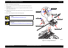
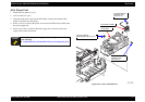
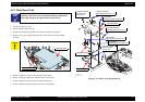
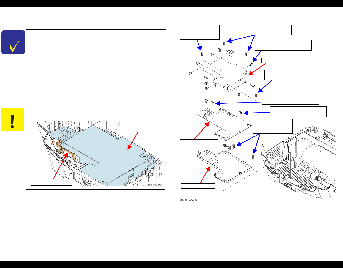
4.6.3 Main Board Unit
1. Panel Unit Removal. (p41)
2. Remove the SC detector lever.
3. Remove all connectors and FCC that connect to main circuit board.
4. Remove six screws on the main board unit, and remove it from the middle
housing.
5. Remove eight screws that secure the upper shield plate.
6. Remove the upper shield plate from the main circuit board.
7. Remove three screws that secure the main circuit board.
8. Remove the main circuit board from the lower shield plate.
Figure 4-23. Main Circuit Board Removal
C H E C K
P O I N T
If you can read EEPROM on the main circuit board before
replacing, repair time can be reduced by backing up adjustment
values, and writing in the replaced main circuit board.
C A U T I O N
Do not touch stacker detector lever when removing.
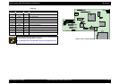
Main Board Unit
Stacker Detector Lever
Upper Shield Plate
Main Circuit Board
lower shield plate
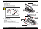
C.B.P Tite 3x10,F/ZN
Tightening torque:0.5 ± 0.1 N
⋅m
C.B.S Tite 3x6,F/ZN
Tightening torque
:0.5 ± 0.1 N
⋅m
C.B.P Tite 3x10,F/ZN
Tightening torque
:0.5 ± 0.1 N
⋅m
C.B.P Tite 3x10,F/ZN
Tightening torque:0.5 ± 0.1 N
⋅m
C.P 3x6,F/ZN
Tightening torque:0.3 ± 0.05 N
⋅m
C.P 3x12,F/ZN
Tightening torque:0.3 ± 0.05 N
⋅m
C.P 3x6,F/ZN
Tightening torque:0.3 ± 0.05 N
⋅m