


EPSON Stylus PHOTO RX600/610, RX620/630 Revision C
Disassembly and Assembly Disassembly and Assembly of Other Parts 62
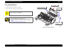
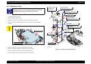
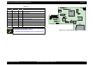
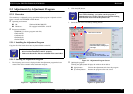
Figure 4-24. Connector Diagram
Table 4-4.
CN No. Color Pins Connection Point
CN3 White 14 Power Unit
CN4 (FFC) 25 CCD Module
CN5 White 5 TPU Inlet Holder
CN6 Red 4 Scanner Motor
CN7 White 3 HP sensor circuit board
CN8 (FFC) 30 Panel circuit board
CN10 White 3 Detector circuit board
CN11 Black 4 CR Motor
CN12 White 4 PF Motor
CN13 (FFC) 19 Print Head
CN14 (FFC) 25 Print Head
A D J U S T M E N T
R E Q U IR E D
When replacing the C543 main circuit board, refer to the following
for replacement and adjustments of parts.
Adjustment Items for Individual Units and Components (p65)