


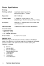

Interface Specifications
The printer has the following resident interfaces:
• Parallel
• RS-232/RS-422 serial
l AppleTalk
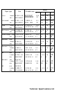
Parallel interface
Your printer is equipped with an B-bit parallel interface.
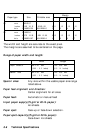
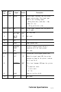
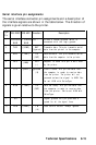
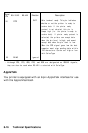
Pin assignments for the parallel interface
The parallel interface connector pin assignments and a description
of the interface signals are shown in the table below.
Signal Return
Pin Pin
Signal Direction
Description
1
19
STROBE IN
The STROBE pulse to read data in. Pulse
width must be more than 0.5
microseconds at the receiving terminal.
2
20
DATA 1
IN
These signals represent Information of
3
21
DATA 2
IN
the 1st to 8th bits of parallel data,
4 22 DATA 3 IN
respectively. Each signal
IS
at HIGH level
5
23
DATA 4
IN
when data is logical 1 and at LOW level
6
24
DATA 5 IN
when it is logical 0.
7
25
DATA 6 IN
a
26
DATA 7 IN
9
27
DATA 8
IN
10
28
ACKNLG
OUT
About a 10-microsecond pulse. LOW
indicates that data has been received
and that the printer is ready to accept
more
data.
This signal is output as a pair
with BUSY.
8-10 Technical Specifications