


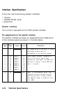
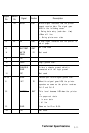
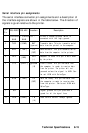
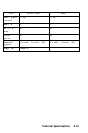

Serial interface pin assignments
The serial interface connector pin assignments and a description of
the interface signals are shown in the table below. The direction of
signals is given relative to the printer.
Signal
Pin
RS-232C RS-422 Direction
Description
1
CHASSIS CHASSIS -
Printer’s chassis ground, which is
GND
GND
connected with the logic ground.
2
TXD
(SYNC)
OUT
Transmits data. This pin transmits serial
(Ignored)
data from the printer to the computer.
3
RXD
(TXD-) IN
Received data. This pin transmits serial
(OUT)
data from the computer to the printer.
4
RTS
(GND)
OUT
Request to send This pin
IS
held HIGH
(-)
by the printer.
5
CTS
(RXD-) ignored
Clear to send. This pin indicates that
(IN)
the computer is ready to receive data
from the printer. The printer will not
proceed unless the signal is HIGH. Can
be set HIGH with SelecType.
6
DSR
(TXD+) IN
Data set ready. This pin indicates that
(OUT)
the computer
IS
ready to receive data
from the printer. Can be set HIGH with
SelecType.
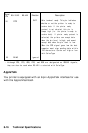
7
SG
Signal ground This pin provides a
ground for all the signal lines.
8
DCD
(RXD+) IN
Data carrier detect. Always ignored.
(IN)
Technical Specifications
8-15