


Pressure Systems, Inc. 98RK-1 & 9816 User’s Manual©
Page 120 www.PressureSystems.com
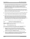
5.1.4 Replacement of Transducers
Model 9816 has internal DH200 pneumatic transducers, as well as an internal calibration
manifold with associated valves and O-rings. Some these elements occasionally require
service or replacement as described in the following sections.
Following is a step-by-step procedure to replace a DH200 transducer in a Model 9816
Intelligent Pressure Scanner. Use the tools and follow the general warnings already
described in Section 5.1.1.
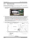
(1) Disassemble the module as described in Section 5.1.2. Remove the transducer/cal-valve
housing from the top chassis rail.
(2) Remove the PC-206 Amplifier/Multiplexer board as described in Section 5.1.3.1. Lay
the circuit board aside on an anti-static surface.
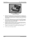
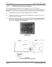
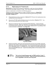
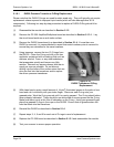
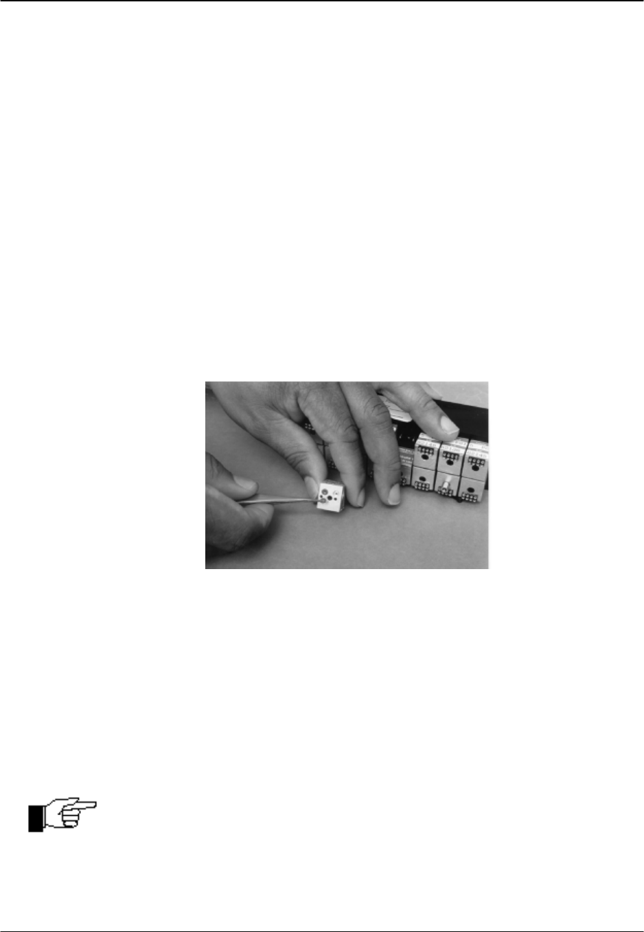
(3) Remove the retaining screw from the desired DH200 transducer. Lift the transducer
straight up to remove it. Make sure that the two (2) O-rings remain with the transducer as
it is removed from the adapter plate. Ensure that the adapter plate O-ring sealing surface
is clean and free of contaminants. See Figure 5.8.
Figure 5.8
Top View of DH200
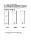
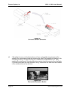
(4) Replace the DH200, making sure that the electrical connections are located on the outer
edge of the cubic design. Be sure that the two (2) O-rings are in place on the DH200 and
that O-ring surfaces are free of contaminants. The O-rings should be lightly greased with
Krytox
®
fluorinated grease. The DH200 must fit the guiding pins smoothly and be aligned
with all other DH200 transducers. Tighten the retaining screw to 40 inch-ounces ±5 inch-
ounces of torque.
Note
The hex-head standoff screws used on DH200 positions 2 and 15
are used to secure the PC-206. These hex-head screws should not
be over tightened or else the screw may break.