


Pressure Systems, Inc. 98RK-1 & 9816 User’s Manual©
Page 19 www.PressureSystems.com
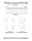
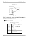
2.3.4 Pressure Connections
Pneumatic connections for the sixteen (16) measurement inputs of the Model 9816 Intelligent
Pressure Scanners installed in the 98RK-1 Scanner Interface Rack may be found either on the
backplane of the 98RK-1 chassis or on the 9816 front plate, depending on the particular
configuration you ordered. Additional control, purge, and calibration inputs are found on the
rear of the 98RK-1. The function of each input port is clearly engraved or printed next to each
input (see Figures 2.2, 2.3 and 2.3a, next page). Connections are through bulge tubing,
compression fittings, or special user-supplied fittings on the tubing plate. All pneumatic inputs to
these modules should contain dry, non-corrosive gas only.
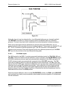
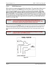
As a standard, all Model 9816 Intelligent Pressure Scanners are supplied with the purge/leak
check calibration manifold. Through software commands to each 9816, this valve may be
placed in one of four positions; RUN, CAL, PURGE, or LEAK-CHARGE. See functions 0C
and 12 of the Set/Do Operating Options/Functions (‘w’) command in Chapter 3 for more
information. Pneumatic input requirements for these four operating positions are described in
following sections.
Here are some guidelines which should be followed when installing pressure connections to all
NetScanner
™
System Intelligent Pressure Scanner modules.
● It is always a good idea to wear certified safety glasses when working with pressurized
lines.
● Ensure that your input pressure will not exceed the proof pressure ratings of the
corresponding instrument transducer. Applying excessive pressure to measurement
inputs can permanently damage the pressure transducers.
● Ensure that all tubing material is rated for the expected pressure and environmental
conditions. Failure to use the proper tubing material may result in ruptured lines and
possible personal injury.
● Ensure all high pressure lines are properly secured.
● Place retaining springs over all bulge tube fittings to ensure pneumatic lines remain
attached and leak free. Springs should be pushed down on connections so that half of
the spring length extends past the tube bulge.
WARNING: Introduction of contaminants to the module pneumatic inputs may
damage transducers, manifolds, and O-ring seals.