


Pressure Systems, Inc. 98RK-1 & 9816 User’s Manual©
Page 32 www.PressureSystems.com
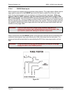
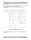
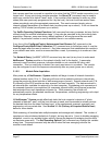
From this schematic, it should be clear that the command letter (c) is required, the position field
(ppppp) immediately follows it, and may have 0, 1, 2, 3, 4, or 5 characters, and there may be
zero or more datum fields ( dddd), as required. For simplicity, the variable length nature of each
"dddd" string is not shown [with brackets] above, but the required leading space character is
shown. The position field is similarly simplified (as “ppppp”) below.
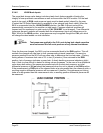
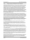
A typical UDP/IP command (contained in the data field following a UDP packet header) is also a
variable length character string, but has a simpler format. Generally, it has a variable length
command string (cccccc), followed by one optional datum ( dddd) field (preceded by one space
character):
“cccccc[ dddd]”
Since there are only a few simple UDP/IP commands, all references to commands below should
assume TCP/IP commands, unless otherwise indicated.
3.1.3.2 Command Field
All NetScanner
™
System models recognize a set of predefined commands. Most are TCP/IP
commands having only a single alphabetic letter for a command field. These are recognized
only when a formal socket connection is established with the host computer. A few are UDP/IP
commands with a longer command field. These are recognized anytime the module has power
applied. All commands are functionally summarized in the following sections and detailed in
reference Section 3.2.
3.1.3.3 Position Field
For some commands, the position field (ppppp) may be broken into other distinct independent
subfields (e.g., xxyyzzf) and these subfields may or may not relate to any datum fields. In other
commands, there may be a 1-to-1 correspondence between ‘1’ bits in the position field (viewed
as a binary bit map expressed as a hex number) and the number of datum fields that follow it (or
the number of datum fields returned in the command’s response). The bit map form is
explained below.
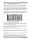
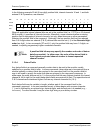
All NetScanner
™
System (Model 9816) Intelligent Pressure Scanner models may contain a
maximum of sixteen (16) internal and two (2) external (rack) input channels. When commands
affect certain channels scanned by the module, the position field is used to identify those
channels as bits in a bit map. If a channel’s corresponding bit in the position field is set to a one
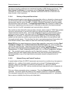
(1), then that channel is affected by the command. The least-significant (rightmost) bit 0
corresponds to Channel 1, and the most significant (leftmost) bit 15 corresponds to the highest
internal Channel 16. Special external (98RK-1 rack) channels, that a Model 9816 can also
scan, require two additional bits (in one more 4-bit hex digit in the bit map shown highlighted
below). Bit 16 (Channel S) specifies the 98RK-1 rack’s source air transducer and Bit 17
(Channel P) specifies the purge transducer. Bits 18 and 19 will remain unused (must be=0)
unless they become defined in a future software release.