Installation, cont’d
CrossPoint 450 Plus and MAV Plus Switchers • Installation
2-10
PRELIMINARY
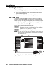
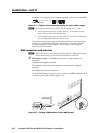
Reset button
j
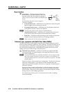
Reset button — The Reset button initiates four
levels of reset to the matrix switcher. Press and
hold the button while the switcher is running or
while you power up the switcher for different reset
levels.
See Performing soft system resets in chapter 3,
Operation, for details.
• Events (mode 3) reset — Hold Reset for 3 seconds then release and push
again to toggle events monitoring on and off.
• IP settings (mode 4) reset — Hold Reset for 6 seconds then release and
push again to reset the switcher’s IP functions.
N
IP settings reset does not replace any user-installed fi rmware.
• Absolute (mode 5) reset — Hold Reset for 9 seconds then release and
push again to restore the switcher to the default factory settings.
• Hard reset — Hold Reset while powering up the switcher to restore the
switcher to the default base fi rmware, user settings, and fi les.
N
Hard reset does not clear the current confi guration.
External sync (systems with MAV Plus Video BMEs)
The MAV Plus Video switcher BME switches between inputs during the vertical
interval period, resulting in glitch-free video switching. The MAV switcher can use
an external signal to synchronize switching during the vertical interval. Without
the external sync locking feature, switching between inputs can result in a brief
rolling (sync loss) or a brief change in the picture size.
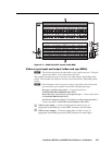
k
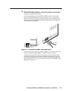
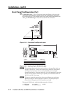
Ext(ernal) Sync connector — Connect an external sync signal to this BNC
connection on BNC 0 for genlocking the video signal in broadcast or other
sync-critical applications.
N
In systems with multiple low resolution video BMEs (such as component video
and S-video systems), only the External Sync connector on the luminance (Y)
video plane’s BME needs to be connected to the black burst generator. This BME
should be BME 0
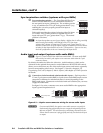
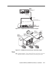
Figure 2-12 shows a basic external sync confi guration. The Ext Sync connector
receives the timing signal. A tee connector on the connector allows the
signal to be passed on to another video device, if required. Terminate the tee
connector if desired.
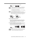
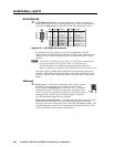
Figure 2-13 shows another confi guration, in which the timing source passes
through three video cameras and a video scan converter before connecting
to the switcher. This type of video camera can synchronize with the external
timing source for video editing applications.
If no external sync timing source is connected to the switcher, switching
occurs immediately.
RESET
Rx


