CrossPoint 450 Plus and MAV Plus Switchers • Quick Start
QS-2
PRELIMINARY
Quick Start — CrossPoint 450 Plus
and MAV Plus Switchers, cont’d
Step 4 — Outputs
a. Video and sync BMEs — Connect a single
plane of video or sync, as appropriate to the
BME, to the BNC connectors on the video
and sync BMEs for each output.
N
Each BME supports one video or sync
plane only. See fi gure 1-1 in chapter 1 for
an example confi guration.
b. Audio BME — Connect balanced or
unbalanced stereo audio or mono audio
devices, as appropriate to the BME type, to
the captive screw connectors.
Step 4 — RS-232/RS-422
If desired, connect a control system or computer
to the Remote RS-232/RS-422 port.
Step 5 — Ethernet
If desired, connect a network WAN or
LAN hub, a control system, or computer
to the Ethernet RJ-45 port. See chapter 2,
Installation, for details.
• Network connection — Wire as a patch
(straight) cable.
•
Computer or control system connection —
Wire the interface cable as a crossover
cable.
Step 6 — Power
Plug the switcher into a grounded AC source.
Unbalanced Stereo Output
Tip
See caution
Sleeve
Tip
See caution
Balanced Stereo Output
Tip
Ring
Sleeve(s)
Tip
Ring
C Connect the sleeve to ground.
Connecting the sleeve to a negative (-)
terminal will damage the audio output
circuits.
Mono Output
Tip
Ring
Sleeves
0.2” (5 mm) max.
Do not tin the wires!
Front Panel Controls
Input and output buttons select inputs and
outputs. Output buttons light amber to
indicate video and audio ties. The buttons
light green to indicate video-only ties. The
buttons light red to indicate audio-only ties.
Input and output buttons also select presets.
The output buttons also display the selected
input’s audio level.
The input buttons also display the selected
output’s volume level.
Enter button saves changes.
Preset button saves a confi guration as a preset or
recalls a previously-defi ned preset.
View button selects a view-only mode
that prevents inadvertent confi guration
changes. In systems with audio BMEs, View
decrements the level and volume.
Esc button cancels selections in progress and
resets the front panel button indications.
The Esc button does not reset: the current
confi guration, the RGBHV and audio
selection, any presets, or any audio level
or volume settings. In systems with audio
BMEs, Esc increments the level and volume.
RGBHV and Audio buttons select/deselect
video and/or audio. The Audio button blinks
to indicate audio breakaway. The Audio
button also selects the audio level/adjust mode.
Create a tie
1. Press and release the
RGBHV and/or Audio
I/O button(s) to select
or deselect video
and/or audio as
desired.
2. Press and release the
desired input button.
3. Press and release the desired
output button(s).
4. Press and release the Enter button.
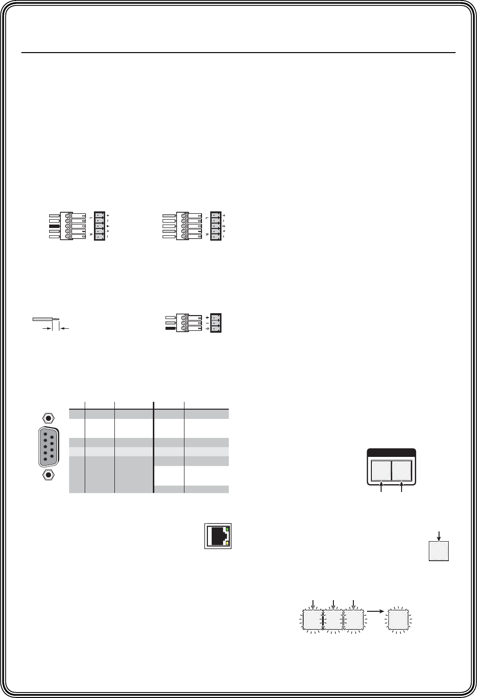
RS-232 Function Pin Function
1
2
3
4
5
6
7
8
9
—
TX
RX
—
Gnd
—
—
—
—
Not used
Transmit
Receive
Not used
Ground
Not used
Not used
Not used
Not used
—
TX–
RX–
—
Gnd
—
RX+
TX+
—
Not used
Transmit (–)
Receive (–)
Not used
Ground
Not used
Receive (+)
Transmit (+)
Not used
RS-422
5
1
9
6
I / O
RGBHV AUDIO
Green = selected.
Off = deselected.
Red = selected.
Off = deselected.
3 4
ENTER
8
Amber indicates RGBHV/video and audio tie.
Green indicates RGBHV/video only tie.
Red indicates audio only tie.
Green indicates the need
to confirm the change.
5
The button lights to
indicate the selection.


