


Operation, cont’d
CrossPoint 450 Plus and MAV Plus Switchers • Operation
3-8
PRELIMINARY
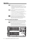
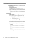
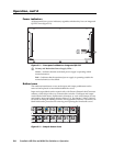
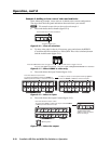
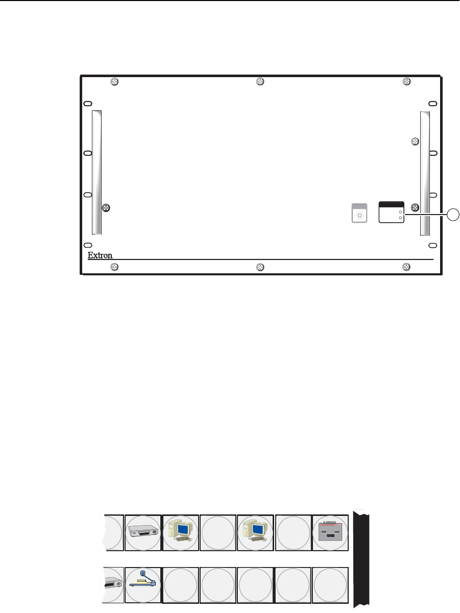
Power indicators
All front panels have power indicators, regardless whether they have an integrated
QS-FPC or not (fi gure 3-2).
MAV PLUS SERIES
AUDIO MATRIX SWITCHER
POWER SUPPLY
PRIMARY
REDUNDANT
I/O CONFIG
9
Figure 3-2 — Front panel without an integrated QS-FPC
i
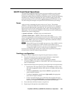
Primary and Redundant Power Supply LEDs —
Green — Indicates that the associated power supply is operating within
normal tolerances.
Red — Indicates that the associated power supply is operating outside the
normal tolerances or has failed.
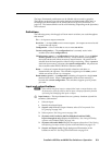
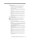
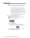
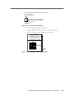
Button icons
The numbered translucent covers on the input and output pushbuttons can be
removed and replaced to insert labels behind the covers.
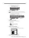
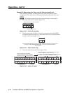
Input and output labels can be created easily with Extron’s Button-Label Generator
software, which ships with every Extron matrix switcher. Each input and output
can be labeled with names, alphanumeric characters, or even color bitmaps for easy
and intuitive input and output selection (fi gure 3-3). See chapter 5, Matrix Software,
for details on using the labeling software. See Appendix B, Reference Information, for
blank labels and a procedure for removing and replacing the translucent covers.
DVD
VCR
Computer Computer
Document
Camera
VTG 200
1
0 13 15
29 28 30 31 32
I
N
P
U
T
S
Figure 3-3 — Sample button icons