


IPI 100 AAP, IPI 200 AAP Series • Installation
2-7
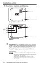
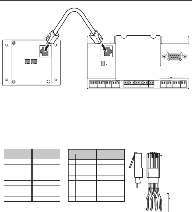
IPI Rear Panel Features and Cabling
Ä
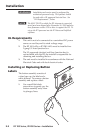
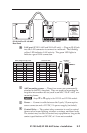
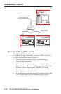
Intercom port (IPI 101 AAP and IPI 104 AAP only) — This port
is used for power, control, and voice data communication with
the MLC. Plug one end of a standard, straight through, CAT 5,
CAT 5e, or CAT 6 cable terminated with RJ-45 connectors into
this port. Plug the other end of the cable into the Intercom
connector on the MLC 226 IP’s rear panel, as shown in the
following gure.
N
A 12” (30.5 cm) CAT 6 cable is included with each IPI. If
you choose to terminate your own cable, the cable must be
no longer than 100’ (30.4 m).
Cables must be terminated to the T586A or T586B
standard and both ends of a cable must be wired to the
same standard.
HOST
CONTROL
R
1=DIGITAL I/O
2=Tx 3=Rx 5=GND
38400, N, 8, 1
PRESS TAB WITH
TWEEKER TO REMOVE
INTERCOM
AUDIO
OUT
LAN
IPI 101 AAP or IPI 104 AAP
Rear Panel
MLC 226 IP Rear Panel
<100’ (30.4 m)
Å
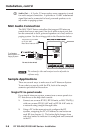
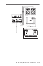
LAN port (IPI 201 AAP and 204 AAP only) — Plug an RJ-45 jack
into the LAN connector to connect to a network. The blinking
yellow LED indicates LAN activity. The green LED lights to
indicate a good LAN connection.
b
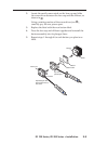
AAP mounting screws — These four screws are permanently
attached to the IPI’s faceplate. They are used for mounting the
faceplate into another device (such as an MLC 226 IP AAP) or a
mounting frame.
N
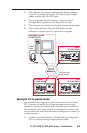
Steps
c
to
e
apply to the IPI 201 and IPI 204 models.
c
Power — Connect a cable between the 2-pole, 3.5,mm captive
screw connector and a 12 VDC, 2 A power supply (included).
d
Contact Relay — The contact relay connector is used to control
items such as room lighting, window coverings, and door locks.
The contact may be used to control any equipment as long as the
contact specications of 24 VDC at 1 A are not exceeded.
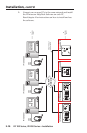
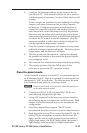
Patch (straight-through) cable
Side 1 Side 2
Pin Wire color Pin Wire color
1 White-orange 1 White-orange
2Orange 2Orange
3 White-green 3 White-green
4 Blue 4 Blue
5 White-blue 5 White-blue
6 Green 6 Green
7 White-brown 7 White-brown
8 Brown 8 Brown
Crossover cable
Side 1 Side 2
Pin Wire color Pin Wire color
1 White-orange 1 White-green
2Orange 2 Green
3 White-green 3 White-orange
4 Blue 4 Blue
5 White-blue 5 White-blue
6 Green 6Orange
7 White-brown 7 White-brown
8 Brown 8 Brown
Clip Down
Side
1
1&2
3&6
4&5
7&8
2345678
Pins
12345678
RJ-45
connector
Twisted
Pairs