


IPI 100 AAP, IPI 200 AAP Series • Installation
Installation, cont’d
2-8
e
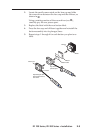
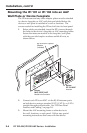
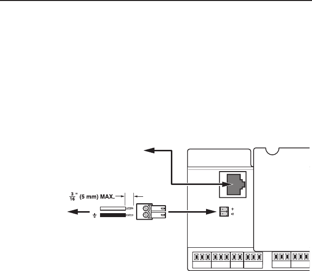
Audio Out — A 3-pole, 3.5 mm captive screw connector is used
for audio output connection. It provides a -10 dBV unbalanced
signal that can be connected to local, powered speakers or to
any audio or paging system.
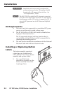
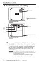
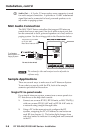
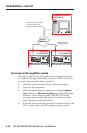
MLC Audio Connection
The MLC 226 IP Series controllers that support IPI intercom
panels also have a rear panel, line level audio output port that
can be connected to local, powered speakers or to any audio or
paging system. See the wiring guide in the illustration below.
MLC 226 IP Rear Panel MLC 226 IP Rear Panel
R
INTERCOM
AUDIO
OUT
To/from the IPI 104 AAP
or IPI 101 AAP
Rear Panel Intercom Port
To a Speaker,
Audio System, or
Paging System
Captive Screw
Connector
+
Do not tin the wires!
N
The volume for this audio output can be adjusted via
software only.
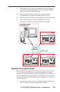
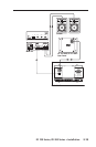
Sample Applications
There are several ways to make use of an IP Intercom System.
To see what you can do with the IPIs, look at the sample
scenarios provided in this section.
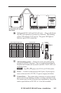
Single PC-to-panel mode
For a simple intercom system, connect one or more panels to a
PC that serves as the help desk console.
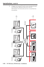
1.
Connect one or more IPI 201, IPI 204 units, or MLC 226 IP(s)
with one or more IPI 101 AAP and/or IPI 104 AAP units
to
a network using straight-through cable.
2. Using a PC in the same network, congure the IPI
systems, assigning the PC’s IP address to one button on
each IPI (see chapter 4 )
. The button light changes from
red tolow amber to indicate it is congured and connected
to the PC.