


IPI 100 AAP, IPI 200 AAP Series • Installation
Installation, cont’d
2-12
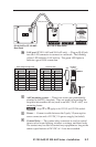
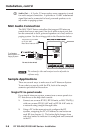
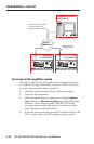
Intercom with amplifier mode
The MLC’s Audio Out 2-pole captive screw connector outputs
a -10 dBV audio signal that can be routed to an MPA 122 or any
external audio amplier, then to speakers.
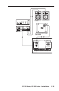
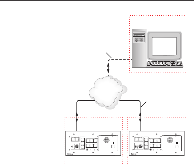
1. Cable the system as shown in the following diagram.
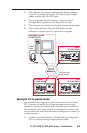
2. Power on the equipment.
3. Make ne adjustments to output level using the Remote
Line slider in the Advanced Settings part of the HelpDesk
software. The external amplier (the MPA 122 in this
example) must be adjusted properly to avoid any audio
signal clipping or audio distortion.
4. If desired, use the software to adjust to minimum levels the
MLC’s audio output, the IPI’s speaker output, or both.
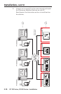
TCP/IP
Network
Configuration Console PC
IP 10.XX.XX.01
Classroom
IP 10.XX.XX.02
MLC 226 IP AAP IPI 101 AAP
PROJECTOR
1
2
3
4
5
6
VOLUME
CONFIG
IR
ON
OFF
AUTO
IMAGE
MUTE
LAPTOP
VCR
DVD
AUX
VIDEO
PC
MLC 226 IP
INTERCOM
MIC ON
LEVEL
HIGH
MED
LOW
IPI 101
PUSH TO
TALK
HELP
DESK
Lab
IP 10.XX.XX.03
Straight-through
Network Cable
MLC 226 IP AAP IPI 101 AAP
PROJECTOR
1
2
3
4
5
6
VOLUME
CONFIG
IR
ON
OFF
AUTO
IMAGE
MUTE
LAPTOP
VCR
DVD
AUX
VIDEO
PC
MLC 226 IP
INTERCOM
MIC ON
LEVEL
HIGH
MED
LOW
IPI 101
PUSH TO
TALK
HELP
DESK
Connect for configuration.
This connection is not
needed for later operation.