


2-5
IPL T S Series • Installation and Operation
IP
L
T
S
2
1
R
100
COM
TX
LINK
ACT
2
RX
RTS
CTS
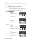
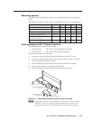
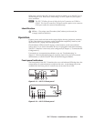
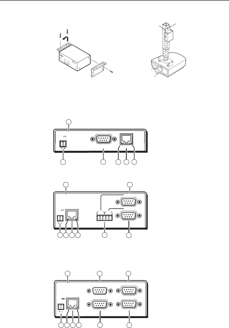
Furniture Mount
Projector Mount
IPL T S2
1
R
100
COM
TX
RX
RTS
CTS
LINK
ACT
2
2
4
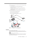
Digital Projector
Mounting
Bolt
Projector
Mounting
Bracket
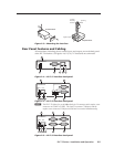
Figure 2-3 — Mounting the interface
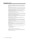
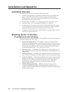
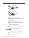
Rear Panel Features and Cabling
All connections, including power, control, input, and output, are on the back panel
of the IPL T S interface. See figures 2-4, 2-5, 2-6, 2-7 for details on each model.
12V
0.5 A
LAN
COM1
00-05-A6-00-00-01
1
32 4
6
10
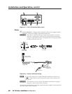
Figure 2-4 — IPL T S1 interface back panel
COM1
LAN
00-05-A6-00-00-02
POWER
12V
.5A MAX
COM1
TX RX TX RX
COM2
COM2
10 6
1
7
532 4
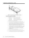
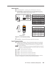
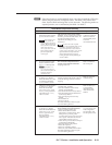
Figure 2-5 — IPL T S2 interface back panel
N
The IPL T S2 allows for use of either the 9-pin D connector or the captive screw
connector on COM1 or COM2. The 9-pin D connector COM ports and the
captive screw connector COM ports should not be connected simultaneously.
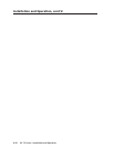
COM3
LAN
00-05-A6-00-00-04
POWER
12V
.5A MAX
COM4
COM1
COM2
1
7
32 4
9
10
6 8
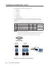
Figure 2-6 — IPL T S4 interface back panel