


IPL T S Series • Connection and Configuration
3-2
Connection and Configuration
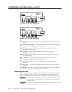
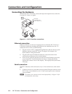
Connecting the Hardware
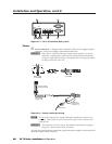
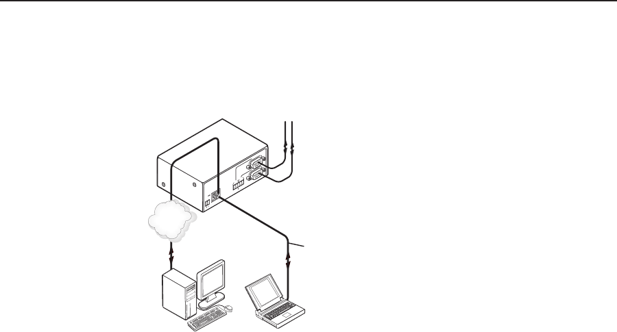
To connect the IPL T S interface, connect the input and output devices to the unit.
Use figure 3-1, below, as a guide.
COM 1
LAN
UID# 093012052
PO
W
ER
12V
.5A MAX
COM1
TXRX
TX
RX
COM2
COM 2
Extron
IPL T S2
Ethernet Control
Interface
Ethernet
TCP/IP
Network
Laptop
PC
or
Serial Cables
to Controlled Devices
(switcher, projector, etc.)
Crossover
Cable
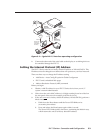
Figure 3-1 — IPL T S interface connections
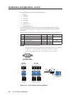
Ethernet connection
Ethernet connection is used on an ongoing basis to connect the IPL T S unit to a
LAN and to control the switching and display devices attached to the unit. To
connect the unit to a LAN, do the following:
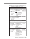
1. Plug one end of a CAT 5, straight-through Ethernet cable into the rear panel
Ethernet connector on the IPL T S unit. See figure 2-9 in chapter 2 for
RJ-45 connector wiring information.
2. Plug the other end of the Ethernet cable into a network switch or hub
connected to an Ethernet LAN or to the Internet.
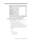
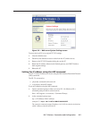
3. From your PC, launch a Web browser and type in the IP address previously
set up on the IPL T S (if this hasnt been set up, see “Setting the Internet
Protocol (IP) Address” later in this chapter). This displays the System Status
Web page.
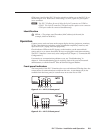
Serial connection
The IPL T S interface can be connected to any A/V device that has a serial control
port.
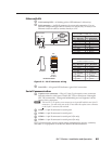
1. Connect one end of a serial cable to the rear panel COM port connector of the
IPL T S unit. As an alternative, use a 3.5 mm, 5-pole captive screw connector
where available.
N
This captive screw connector must be wired appropriately. See figure 2-10 for
pin assignments, if necessary.